Interested in building a pure sine wave inverter? This article provides a comprehensive guide to designing and implementing such a device using the PIC16F76 microcontroller. Pure sine wave inverters are essential in many power electronics applications, offering superior performance compared to modified sine wave inverters. This project offers a hands-on learning experience, enabling you to build a functional inverter and understand the underlying principles. Read on to discover the process.
⚠️Disclaimer:
Working with electricity involves serious risk. Ensure you have the necessary skills and take proper safety precautions before attempting any electrical projects. Proceed at your own risk — the author assumes no responsibility for any damage, injury, or issues resulting from the use or misuse of the information provided.
All content on this website is original and protected by copyright. Please do not copy or reproduce content without permission. While most of the resources shared here are open-source and freely accessible for your learning and benefit, your respect for our intellectual effort is appreciated.
If you find our tutorials helpful, consider supporting us by purchasing related materials or sharing our work — it helps keep the content flowing.
Need help or have questions? Leave a comment below — the author is always happy to assist!
Table of Contents
Sine wave inverter mechanism:
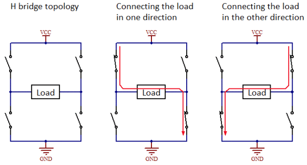
In most of the cases in sine wave inverters, an H-bridge driving configuration is used. There are four sets of switches that are connected like an H like in this image:
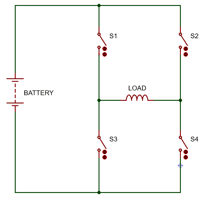
Here there are 4 switches S1 to S4. By switching in the sequential way we can generate an alternating current flow through the load. It is like this:
An alternating current flow generates an alternating voltage across the load. And if this load is a step-up transformer, then we can get an alternating voltage across the secondary of the transformer which will be higher than the supply voltage. This is the basic configuration of the inverter.
Now if you drive this H-bridge with an SPWM signal, an SPWM can be found on the higher voltage end of the transformer. After filtering that, we can easily get a pure sine wave. This is the concept of a sine wave inverter.
SPWM generation for sine wave:
Before we start, you should read my previous article to understand how we can use the PIC16F76 microcontroller to generate an SPWM signal.
Now our main job is to generate SPWM using a PIC microcontroller. Then we can use this SPWM signal to drive our H-bridge. But to drive the H-bridge, we need two push-pull types SPWM and two push-pull signals like this:


Here, there are two signals at 50Hz in a push-pull configuration, and the other two are SPWM signals (20KHz), which are followed by the previous 50Hz signals. These 4 signals are used to drive the H-bridge. The switches can be MOSFET, IGBT, or transistors. We have to choose a suitable one. For inverters, we can use MOSFETs as our switching devices.
The upper arms of the bridge are switched by a 50Hz signal. And the lower arms are switched by 20KHz modulated signals. We can not use these signals directly to switch the MOSFETs. We need gate driving circuits to convert the signal from the microcontroller to the switch MOSFET. These gate-driving circuits simply convert the MCU’s 5V signal into a 10V+ signal which can be used to switch MOSFETs.

Circuit diagram:
So the circuit diagram for our Pure sine wave inverter using PIC16F76:

Here you can see that all the MOSFETs are driven with the help of the TLP250 gate driver IC and associated circuitry. The control MCU is PIC16F76, which generates 4 sets of signals, and these signals trigger the MOSFETs with the help of the gate driver IC. The MOSFETs are driving our main power transformer, TR1. Which is a UPS transformer rated 7.5v:250v. At the secondary terminal, a high-voltage capacitor C9 is working as our filter (C), and the transformer itself is working as an inductor (L). So an L-C filter is formed in our circuit.
There is another option to add feedback in our inverter, which is designed with a transformer. Although it can be made of electronic circuits only to keep it simple to understand, I kept transformer TR2.
Also, to measure the battery voltage, I used a voltage divider circuit with R18 & R19+C14. To turn the inverter on/off, a switch is used which is connected to the RA4 pin of our MCU.
Before we start the coding, you should read my previous article to understand how we can use the PIC16F76 microcontroller to generate an SPWM signal.
Coding:
Here is our code to drive the H-bridge from where we expect to get a pure sine wave.
/*******************************************************************************
* Program for sine wave generation using PIC16F73                              *
* Program Written by_ Engr. Mithun K. Das                                      *
* MCU:PIC16F76; X-Tal:20MHz; mikroC pro for PIC v7.6.0                         *
* Date:18-04-2020                                                              *
*******************************************************************************/

unsigned char sin_table[32]={0, 25, 49, 73, 96, 118, 139, 159, 177, 193, 208, 220, 231, 239, 245, 249, 250, 249, 245, 239, 231, 220, 208, 193, 177, 159, 139, 118, 96, 73, 49, 25};
int duty=0;
float fb_constant=0.8;
bit alt;
bit inv_mask;
void Interrupt() iv 0x0004 ics ICS_AUTO
{
   if (TMR2IF_bit == 1)
   {
      duty++;
      if(duty>=32)
      {
        duty=0;
        alt=~alt;
        CCPR1L = 0;//inverter shutdown
        CCPR2L = 0;
        RC0_bit=0;
        RC3_bit=0;
        asm nop;
        asm nop;
      }

      if(inv_mask)
      {
          if(alt)
          {
             CCPR1L = sin_table[duty]*fb_constant;
             CCPR2L=0;
             RC0_bit=1;
             RC3_bit=0;
          }
          else
          {
             CCPR2L = sin_table[duty]*fb_constant;
             CCPR1L=0;
             RC0_bit=0;
             RC3_bit=1;
          }
      }
      else
      {
         CCPR1L = 0;//inverter shutdown
         CCPR2L = 0;
         RC0_bit=0;
         RC3_bit=0;
      }
      TMR2IF_bit = 0;
   }
}

int k=0;
unsigned int battery=0,output=0;
bit lcd_clr;
char msg[]="000";

void main()
{
   TRISA=0xFF;//all input
   TRISC = 0x00;//all output
   PORTC=0x00;
   RC4_bit = 1;//for LCD backlight
   ADC_Init();
   PR2 = 249;
   CCP1CON = 0x4C;
   CCP2CON = 0x4C;
   TMR2IF_bit = 0;
   T2CON = 0x2C;
   TMR2IF_bit = 0;
   TRISC = 0;
   TMR2IE_bit = 1;
   GIE_bit = 1;
   PEIE_bit = 1;
   UART1_Init(9600);
   while(1)
   {
      RC4_bit = 1;
      //switch operation
      if(!RA4_bit)
      {
        inv_mask=1;
        lcd_clr=1;
      }
      else
      {
        inv_mask=0;
        if(lcd_clr)
        {
            lcd_clr=0;
            Delay_ms(1000);
        }
      }

      //read output
      output=0;
      for(k=0;k<20;k++)
      {
         output+=ADC_Get_Sample(3);
         Delay_ms(1);
      }
      output/=20;


     if(output<100)
     {
        if(fb_constant<0.7)fb_constant+=0.1;
     }
     if(output>115)
     {
        if(fb_constant>0.5)fb_constant-=0.1;
     }

   }
}// end
This code implements a pure sine wave inverter using a PIC16F76 microcontroller. Here’s a breakdown of its functionality:
1. Sine Wave Generation (Interrupt Service Routine – ISR):
sin_table[32]: This array stores 32 pre-calculated values representing one cycle of a sine wave. These values are used to control the duty cycle of the PWM outputs.- Timer2 Interrupt: The code uses Timer2 to generate interrupts at a specific frequency. This interrupt triggers the sine wave generation process.
dutyVariable: This variable acts as an index to thesin_tablearray, stepping through the sine wave values.altBit: This bit toggles every timedutyit reaches 32 (one full sine wave cycle). It’s used to alternate between the two halves of the H-bridge (controlled by CCP1 and CCP2).inv_maskBit: This acts as an enable/disable switch for the inverter output. Wheninv_maskis 1, the inverter is active; when it’s 0, the inverter is shut down.fb_constantFloat: This variable appears to be an attempt at a simple feedback loop.- PWM Generation (CCP1 and CCP2): Inside the ISR, the code uses the CCP1 and CCP2 modules to generate PWM signals. The duty cycle of these PWM signals is determined by the values in the
sin_tablearray, multiplied by thefb_constant. - H-Bridge Control (RC0 and RC3): The RC0 and RC3 pins control the high and low sides of an H-bridge. The
altbit ensures that only one side of the H-bridge is active at a time, creating the alternating current output. - Shutdown Mechanism: When
dutyreaches 32 or wheninv_maskis 0, the PWM outputs are set to 0, effectively shutting down the inverter.
2. Main Function:
- Initialization:
- Configures I/O pins (TRISA as input, TRISC as output).
- Initializes the ADC module.
- Configures Timer2 for PWM generation.
- Configures the CCP1 and CCP2 modules for PWM mode.
- Enables Timer2 interrupts and global interrupts.
- Initializes the UART1 module for serial communication.
- Main Loop:
- Inverter Enable/Disable (RA4): Reads the state of RA4 to control the
inv_maskbit. This acts as a hardware switch to turn the inverter on or off. - Output Voltage Reading (ADC Channel 3): Reads the output voltage of the inverter using the ADC.
- Feedback Control: Implements a simple feedback mechanism based on the output voltage. If the output voltage is below 100,
fb_constantis increased; if it’s above 115,fb_constantis decreased. This attempts to regulate the output voltage. - LCD and UART Output: The code is set up to output data to an LCD and a UART. This part of the code is not shown in the snippet provided.
- Inverter Enable/Disable (RA4): Reads the state of RA4 to control the
Key Observations and Potential Improvements:
- Simple Feedback: The feedback mechanism is very basic and likely not very effective at regulating the output voltage under varying loads. A more sophisticated control algorithm (e.g., PID control) would be needed for better regulation.
- No Dead Time: The code doesn’t implement any dead time between switching the H-bridge legs. This can lead to a shoot-through current and damage the MOSFETs. Dead time is essential in H-bridge designs.
- Limited Resolution: Using only 32 values in the sine table results in a stepped approximation of a sine wave, which introduces harmonics. A larger table would provide a smoother output.
- No Output Filtering: A proper LC filter at the output of the H-bridge is crucial to remove high-frequency switching noise and produce a clean sine wave.
- No Current Limiting or Overload Protection: The code lacks any protection mechanisms, which can be dangerous in case of a short circuit or overload.
- Floating-Point Inefficiency: Using floating-point multiplication (
* fb_constant) inside the ISR is computationally expensive on a microcontroller. Using integer math with scaling would be more efficient.
In summary, this code provides a basic implementation of a pure sine wave inverter. However, it lacks several important features, such as proper feedback control, dead time, output filtering, and protection mechanisms. These need to be addressed to create a robust and reliable inverter.
Check these:
- Learning PIC Microcontrollers Programming in C: Chapter 1
- Learning PIC Microcontrollers Programming in C: Chapter 2
- Learning PIC Microcontrollers Programming in C: Chapter 3
- Learning PIC Microcontrollers Programming in C: Chapter 4
- Improve your code learning PIC MCU in C: Chapter 5
We are using a switch to turn the inverter on/off, which is controlled by the variable ‘inv_mask’ inside the interrupt routine.
Download the hex file from here for free!
PCB:
I use Sprint-Layout to design PCBs for most of the small projects. Here is the PCB design for our inverter.

Result:
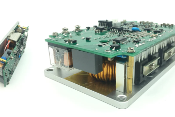
After completing the PCB I tested this project. The result was awesome. Project image:

The waveshape of our sine wave inverter:

My oscilloscope’s voltage sensing is not accurate. I measured with a multi-meter, and I got 210V good AC output. As a small transformer used here, loading over 100 watts significantly reduces output voltage.
Liked this article? Subscribe to our newsletter:
or,
Visit LabProjectsBD.com for more inspiring projects and tutorials.
Thank you!
Read more:
- Learning PIC MCU Chapter 7: How to interface buttons with microcontrollers
- Learning PIC MCU Chapter 6: Interfacing Passive Components with Microcontrollers
- How to reduce noise from DC motor
- Interfacing External EEPROM with PIC microcontroller
Some exclusive inverters:


Ads:

68 Comments
Asimi · 26/07/2020 at 2:57 am
Good day Mr Mithun. I have been writing to severally but the message didn’t deliver and I decided to try it again today. Pls I really appreciate all your efforts in all the post created to help individual who want to learn. May God Almighty reward and give you more knowledge. However, I have been facing a lot of challenges in the sine inverter you have posted. (1) how did you get CCP1CON= CCP2CON= 0x4C; = 0b01001100; from the table, in datasheet. I have spent almost completely full day, I couldn’t get it. Pls show me how you got it. (2) how did you get your PR2 = 251, when using “Fosc = 20MHz and Fpwm = 20Kz respectively. When calculated, I got 249 (I e PR2= 249 not 251). (3) pls, explain to me, how did i develop small code to charge the inverter via mains ac sensing. Is it to keep the 2 of ccp1 and ccp2 active and deactivate the low frequency (50Hz) signal or keep low frequency (50Hz) actively and deactivate ccp1 and ccp2. pls, guide me
Mithun K. Das · 27/07/2020 at 4:37 am
Yes it was 249 if calculated. I was testing tuning a little bit which gave me good result for my circuit and transformer. You can check on your side.
djalltra · 20/10/2020 at 12:07 pm
a million thanks for this tutorial I love your tutorials
Mithun K. Das · 20/10/2020 at 2:12 pm
Thank you too
Emman · 11/04/2021 at 10:52 am
Thank you for this article.
How can we add battery charging code here?
MKDas · 11/04/2021 at 11:18 am
This one is a basic one. If it is utilized and reformated in flat coding, all standard options can be added. I’ll try to do something with this later. Stay with us & subscribe. Maybe in future, you’ll get more useful posts.
enrique · 01/01/2021 at 11:05 pm
excelente, como todos sus trabajos ,desde Colombia gracias
Godwin · 26/02/2021 at 9:02 pm
Please,hex file I didn’t have the compiler
Mithun K. Das · 27/02/2021 at 5:10 am
Install the compiler. Arrange your code. If it shows demo limit, email the complete project file to [email protected]
Ehi · 11/08/2021 at 1:55 am
The drop in voltage when more than 100w is appliedhow can it be corrected
MKDas · 11/08/2021 at 11:39 am
If it is redesigned with feedback then it will work.
manh · 08/05/2021 at 6:38 am
Please help,code file I didn’t have the compiler
MKDas · 08/05/2021 at 7:42 am
Updated
Antonio Franca · 07/07/2021 at 12:58 am
Mithun, thank you very much for your prompt attention. I kindly ask if it is possible for you to change and send me the lines of code referring to the LCD.
Sincerely,
Antonio France
MKDas · 07/07/2021 at 5:08 am
I don’t know the pin configuration of the easy pic. Kindly change it yourself, please.
Antonio França · 07/07/2021 at 11:46 am
Hello Mithun, good morning. Here in Brazil it is 8:45 am
I don’t know which country you reside in.
Returning to the question of your project, I would like if possible to make available to everyone the schematic diagram with the connections with the LCD.
thanks
Antonio França
MKDas · 07/07/2021 at 11:48 am
the diagram is given in the article. Kindly check.
Franca · 07/07/2021 at 1:22 pm
Which Article?
MKDas · 07/07/2021 at 2:40 pm
This article. Kindly check again.
Antonio França · 07/07/2021 at 10:06 pm
Dear MKDas,
Unfortunately I didn’t see in your schematic any connection of the PIC16F73 with any LCD
MKDas · 08/07/2021 at 1:02 am
Oh sorry, I did not check that this one was LED-based. There is another one with LCD based. I’ll make the hardware ready soon, then write on that.
MUNIKO · 17/08/2021 at 4:54 pm
hi,i want to build your circuit but help me to have protections, battery low and overvoltage,short circuit and display,
MKDas · 17/08/2021 at 8:25 pm
First, make this basic one. Then you can add features easily if you understand this.
Muniko · 19/10/2021 at 10:04 pm
Is there a feeback in this circuit?
MKDas · 21/10/2021 at 11:47 am
no
Saddam · 01/11/2021 at 2:06 am
Dear sir aponi ki pic16f73 ic er ips er jonno peogrrame kore dite parben…….
Lab Projects BD · 01/11/2021 at 10:21 am
The same program, Just change the IC in the compiler.
Chimezie · 09/11/2021 at 3:38 pm
Hi please which compiler did you make use of.. and please when are you adding feedback to the design thanks
Lab Projects BD · 09/11/2021 at 9:17 pm
I mentioned in the article. Please read carefully.
Paul · 09/11/2021 at 5:02 pm
hi nice work please i need your assistance to add charging mode to this great project thanks [email protected]
Lab Projects BD · 09/11/2021 at 9:17 pm
In that case, I’ll suggest you use dsPIC.
Prasanjith · 25/03/2022 at 4:07 pm
In your schematic Where is the Low pass filter after generating PWM signals?
MKDas · 26/03/2022 at 12:11 pm
The transformer itself is a big inductor. And just add a capacitor with the output in parallel. So there is a LC filter….
prestley johnson · 10/04/2022 at 1:17 am
hi MKDas, kindly upload video for the spwm inverter.
MKDas · 10/04/2022 at 7:20 pm
I’ll, but not this one. With dsPIC one. 🙂
Achira · 14/04/2022 at 12:30 pm
Dear MKdas,
I would like to make the inverter project. Let me have the PCB pattern as a PDF so that I will be able to make it with the toner transfer method. Also a crystal shown in your assembled photo but its not indicated in the circuit diagram ?
Thank you,
Achira
[email protected]
MKDas · 14/04/2022 at 4:36 pm
Crystal is not shown in the proteus circuit diagram but in real, you have to use one.
Eniola · 21/05/2022 at 5:34 pm
The greatest blog ever,love 💕💕💕 to be in this blog .may take Lord continue to increase your wisdom.love you sir.sir,I want protection for this circuit or can I sense overload for the some port use as input? which port can I sense with overload and short circuit? looking forward to your quick response.i have subscribed to this blog
MKDas · 21/05/2022 at 8:57 pm
You can do anything you want if you understand the working principle and know how to add codes.
Love your blog and May the Lord bless you for helping people like me. Love you sir. Sir, how can I add lcd display to display battery sense, inverter on and off · 07/06/2022 at 10:55 pm
Love your blog and May the Lord bless you for helping people like me. Love you sir. Sir, how can I add lcd display to display battery sense, inverter on and off
MKDas · 08/06/2022 at 9:51 am
Thank you. Yes you can add the LCD display. Simply use the LCD functions from the library. But only one thing you need to keep in mind about the microcontroller’s range of capacity.
Caleb · 17/07/2022 at 4:56 pm
I love your blog keep up the good work. I will update the code and add feedback, short circuit, overload battery low and charging and will upload foe everyone
Mr.PP · 22/07/2022 at 8:22 am
I want the system Soft Start Amplitude from 0-220v how to do? Please advise.
MKDas · 22/07/2022 at 12:34 pm
gradually increase the PWM
Abul Hassan · 09/08/2022 at 8:54 pm
Can this project work in pic16f72 ic?
MKDas · 09/08/2022 at 9:04 pm
No.
Faizan · 06/09/2022 at 11:05 pm
Great
Faizan · 06/09/2022 at 11:06 pm
Can this project work in pic16f873 ic?
MKDas · 07/09/2022 at 4:09 pm
yes, but configuration changes are required.
EMERITUS · 17/01/2023 at 1:18 am
I finally finished the project have completed the feedback section and can power any heavy load with no output drop, added temperature sensor for shutdown while inverting and charging, added charging section to it can charge upto 15A current and doesnt select transformer, added battery low shutdown, mainsdetect and charges commence after 10secs, trickle charger, overload protection, and shut circuit protection all in the pic16f73. you can contact me for the full c-file written in mikroc for pic
MKDas · 17/01/2023 at 10:27 am
Fantastic
Olly · 13/05/2023 at 1:26 pm
Hi, good work and more grace to your elbow. Please can you help with your developed design? Thanks in advance.
MKDas · 13/05/2023 at 3:02 pm
This one is for learning purpose and its open for all. But for professional ones, I recommend dsPIC. And sorry, professional ones are not open source.
Olly · 03/08/2023 at 12:44 pm
Hi Mr Emeritus, you have done a great job to compliment the author of this post.
Please assist me with your design circuit and code just as the author of this post has done. My email is [email protected]. Thanks for the good job.
MKDas · 12/08/2023 at 6:15 pm
plz write what you are asking for.
paul · 14/10/2023 at 5:35 pm
EMERITUS plese i need it
Snehrish · 13/11/2023 at 2:00 am
EMERITUS, please can you email so we can talk about it
[email protected]
MKDas · 13/11/2023 at 11:45 am
if you need to discuss anything, WhatsApp me.
CDTES · 23/06/2024 at 3:09 am
Can I get your whatsapp number, I need the professional one, what will it cost me
MKDas · 23/06/2024 at 1:21 pm
given in the subscription section.
kuldip · 28/03/2023 at 2:28 pm
Sir, PWM signal is not generating from the microcontroller as you have shown here, i have simulated the circuit in proteus but didn’t work, what to do? Please help, sir
MKDas · 29/03/2023 at 11:56 am
check project settings
Alfrever · 25/06/2023 at 9:53 pm
Hello, your design looks very interesting and thanks for sharing it. I am a beginner in programming, what parts of the code would I have to modify to change the frequency to 60Hz?
MKDas · 02/07/2023 at 7:28 pm
Thanks. Edit timer interrupt settings.
paulo obregon · 28/08/2023 at 8:11 pm
ola gostaria de operar em 60 hz ajude-me
MKDas · 04/09/2023 at 8:29 pm
edit timing
Arif · 13/05/2024 at 4:45 pm
Sir, is dead time pwm possible with this IC. For Puspool Transformer ??
MKDas · 16/05/2024 at 1:54 pm
not possible directly. but with code not impossible.