Sometimes, we need to add LCD with the project while the micro-controller itself has limited free pins for LCD. In that case, we can use shift registers to interface LCD with a micro-controller. After reading this article, you’ll be able to do that yourself. It’s easy! So let’s start Interfacing 16×2 LCD with 74HC595.
⚠️Disclaimer:
Working with electricity involves serious risk. Ensure you have the necessary skills and take proper safety precautions before attempting any electrical projects. Proceed at your own risk — the author assumes no responsibility for any damage, injury, or issues resulting from the use or misuse of the information provided.
All content on this website is original and protected by copyright. Please do not copy or reproduce content without permission. While most of the resources shared here are open-source and freely accessible for your learning and benefit, your respect for our intellectual effort is appreciated.
If you find our tutorials helpful, consider supporting us by purchasing related materials or sharing our work — it helps keep the content flowing.
Need help or have questions? Leave a comment below — the author is always happy to assist!
Table of Contents
How to interface LCD?
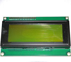
LCD is very common in the electronics arena. Among lots of LCDs, the 16×2 one is the most common one. Technically, most of us know this type of LCD as HD44780 based LCD. Here HD44780 is the interface IC. But in common or people know it in an easy way as 16×2 LCD.
Pin configuration:
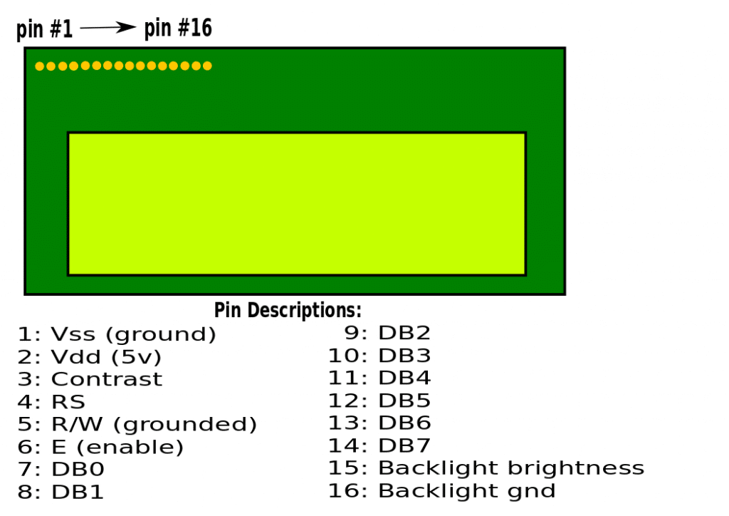
As you see, we have 10 pins for the LCD interface in 8bit mode and 6 for 4bit mode. 8bit mode is not so used in common, 4bit mode is most used. So we need at least 6pins free to interface LCD with our micro-controller.
If the MCU has free pins, that’s fine. But if not then? Yes, then we can use Shift registers to extend some pins!
What is 74HC595 shift register?
In digital circuits, a shift register is a cascade of flip flops, sharing the same clock, in which the output of each flip-flop is connected to the “data” input of the next flip-flop in the chain, resulting in a circuit that shifts by one position the “bit array” stored in it, “shifting in” the data present at its input and ‘shifting out’ the last bit in the array, at each transition of the clock input. _Wiki.
To know more about shift registers, please visit the wiki page here.
You may find this project helpful: How to remove noise/garbage from the HD44780 LCD display
Shift registers are different in type. The most common ones are
- Serial in-parallel out
- Parallel in – Serial out
There are many types of shift registers, which can not be explained in short articles. Please do some research on this issue over the internet.
About 74HC595 Shift Register:
74HC595 is a serial into parallel-out with latch triggered tri-state shift register. This 16pin shift register is very common in use with a micro-controller as a port extender.
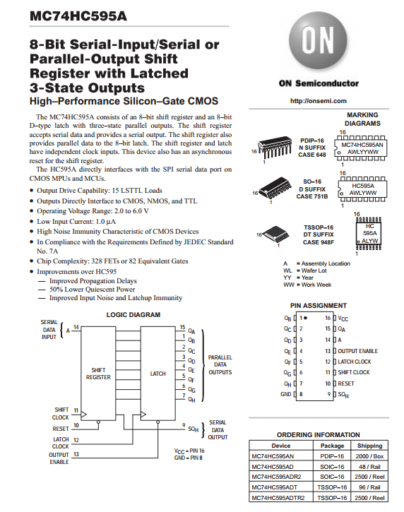

This SIPO shift register has a data input pin (A) where data can be loaded which is controlled by the shift clock. Then one latch clock shifts these data to its output pins according to the 8bit data pattern given serially at the data pin. Output Enable pin (!OE) is active low to enable output of that shift register. And the reset pin is also active low, connecting this reset pin to VDD will keep the operation going on. When we need more outputs, we just connect shift registers in cascade mode. For this, there is a data output (serial data out) pin. This pin will be then connected to the data input pin of the next shift register.
So how to connect Shift register with LCD?
Here is the solution. We can follow this circuit diagram for 4bit mode.

Here, shift register 74HC595 or 74LS595 can be used. Both are ok for this project.
MikroC Coding:
#include"_595_LCD.h"

unsigned char txt[]="mithun060@gmail_";

void main()
{
  TRISIO=0x00;
  GPIO=0x00;
  LCD_init();

  while(1)
  {
     LCD_clear_home();
     LCD_goto(1,1);
     LCD_putstr("HC595 LCD TEST"); //for direct string
     Delay_ms(3000);
     LCD_clear_home();
     LCD_goto(1, 1);
     LCD_putstr(txt); //for string from character array
     LCD_goto(2,1);
     LCD_putstr(".com");
     Delay_ms(3000);

  }
}
Here a header file is used to simplify the coding. This header file can be modified and implemented to other similar micro-controllers.
The header file:
#define clear_display                           0x01
#define goto_home                               0x02

#define cursor_direction_inc                    (0x04 | 0x02)
#define cursor_direction_dec                    (0x04 | 0x00)
#define display_shift                           (0x04 | 0x01)
#define display_no_shift                        (0x04 | 0x00)

#define display_on                              (0x08 | 0x04)
#define display_off                             (0x08 | 0x02)
#define cursor_on                               (0x08 | 0x02)
#define cursor_off                              (0x08 | 0x00)
#define blink_on                                (0x08 | 0x01)
#define blink_off                               (0x08 | 0x00)

#define _8_pin_interface                        (0x20 | 0x10)
#define _4_pin_interface                        (0x20 | 0x00)
#define _2_row_display                          (0x20 | 0x08)
#define _1_row_display                          (0x20 | 0x00)
#define _5x10_dots                              (0x20 | 0x40)
#define _5x7_dots                               (0x20 | 0x00)

#define dly                                     1

#define LCD_SDI   GP1_bit //pin declearations
#define LCD_SCK   GP0_bit
#define LCD_LCK   GP2_bit

#define LCD_SDI_Direction   TRISIO1_bit
#define LCD_SCK_Direction   TRISIO0_bit
#define LCD_LCK_Direction   TRISIO2_bit

unsigned char data_value;

void SIPO();
void LCD_init();
void LCD_command(unsigned char value);
void LCD_send_data(unsigned char value);
void LCD_4bit_send(unsigned char lcd_data);
void LCD_putstr(char *lcd_string);
void LCD_putchar(char char_data);
void LCD_clear_home();
void LCD_goto(unsigned char x_pos, unsigned char y_pos);


void SIPO()
{
    unsigned char clk = 8;
    unsigned char temp = 0;

    temp = data_value;
    LCD_LCK = 0;
    while(clk > 0)
    {
        LCD_SDI = ((temp & 0x80) >> 0x07);
        LCD_SCK = 1;
        temp <<= 1;
        LCD_SCK = 0;
        clk--;
    }
    LCD_LCK = 1;
}


void LCD_init()
{
    unsigned char t = 0x0A;
    data_value = 0x08;
    SIPO();
    while(t > 0x00)
    {
      Delay_ms(dly);
      t--;
    };

    data_value = 0x30;
    SIPO();

    data_value |= 0x08;
    SIPO();
    Delay_ms(dly);
    data_value &= 0xF7;
    SIPO();
    Delay_ms(dly);

    data_value = 0x30;
    SIPO();

    data_value |= 0x08;
    SIPO();
    Delay_ms(dly);
    data_value &= 0xF7;
    SIPO();
    Delay_ms(dly);

    data_value = 0x30;
    SIPO();

    data_value |= 0x08;
    SIPO();
    Delay_ms(dly);
    data_value &= 0xF7;
    SIPO();
    Delay_ms(dly);

    data_value = 0x20;
    SIPO();

    data_value |= 0x08;
    SIPO();
    Delay_ms(dly);
    data_value &= 0xF7;
    SIPO();
    Delay_ms(dly);

    LCD_command(_4_pin_interface | _2_row_display | _5x7_dots);
    LCD_command(display_on | cursor_off | blink_off);
    LCD_command(clear_display);
    LCD_command(cursor_direction_inc | display_no_shift);
}


void LCD_command(unsigned char value)
{
    data_value &= 0xFB;
    SIPO();
    LCD_4bit_send(value);
}


void LCD_send_data(unsigned char value)
{
    data_value |= 0x04;
    SIPO();
    LCD_4bit_send(value);
}


void LCD_4bit_send(unsigned char lcd_data)
{
    unsigned char temp = 0x00;

    temp = (lcd_data & 0xF0);
    data_value &= 0x0F;
    data_value |= temp;
    SIPO();

    data_value |= 0x08;
    SIPO();
    Delay_ms(dly);
    data_value &= 0xF7;
    SIPO();
    Delay_ms(dly);

    temp = (lcd_data & 0x0F);
    temp <<= 0x04;
    data_value &= 0x0F;
    data_value |= temp;
    SIPO();

    data_value |= 0x08;
    SIPO();
    Delay_ms(dly);
    data_value &= 0xF7;
    SIPO();
    Delay_ms(dly);
}


void LCD_putstr(char *lcd_string)
{
    while (*lcd_string != '\0')
    {
        LCD_send_data(*lcd_string);
        lcd_string++;
    };
}


void LCD_putchar(char char_data)
{
    LCD_send_data(char_data);
}


void LCD_clear_home()
{
    LCD_command(clear_display);
    LCD_command(goto_home);
}


void LCD_goto(unsigned char y_pos,unsigned char x_pos)
{

    if((y_pos-1) == 0)
    {
        LCD_command(0x80 | (x_pos-1));
    }
    else
    {
        LCD_command(0x80 | 0x40 | (x_pos-1));
    }
}
Simulation result:
Conclusion:
As you see, we have interfaced 16×2 LCD with PIC12F675 using the 74HC595 Shift register. This concept and the code can be used with any similar micro-controller. Using like this is also known as 3 wite LCD and very useful for many circuits where free pins are limited.
Liked this article? Subscribe to our newsletter:
or,
Visit LabProjectsBD.com for more inspiring projects and tutorials.
Thank you!
Check this out: 5 coolest multimeters you can buy


4 Comments
Joy · 27/11/2020 at 3:42 pm
Dear sir, Please make a video how to create mikro c pro Header file and add main program.
Mithun K. Das · 28/11/2020 at 5:13 am
OK. I’ll try.
saon · 03/03/2023 at 8:47 pm
sir how cna i add header file into MIckro pro? plz tell me.
MKDas · 03/03/2023 at 9:15 pm
google it plz.