We all know about voltmeters. Besides multimeters, there are some panel meters that show voltage, current, etc. Making such an AC voltmeter is sometimes becomes very helpful. Here in this article, we are going to learn how we can make our own single-phase AC voltmeter using a PIC16F76 micro-controller and capacitor power supply. So let’s start!
⚠️Disclaimer:
Working with electricity involves serious risk. Ensure you have the necessary skills and take proper safety precautions before attempting any electrical projects. Proceed at your own risk — the author assumes no responsibility for any damage, injury, or issues resulting from the use or misuse of the information provided.
All content on this website is original and protected by copyright. Please do not copy or reproduce content without permission. While most of the resources shared here are open-source and freely accessible for your learning and benefit, your respect for our intellectual effort is appreciated.
If you find our tutorials helpful, consider supporting us by purchasing related materials or sharing our work — it helps keep the content flowing.
Need help or have questions? Leave a comment below — the author is always happy to assist!
Warning!: The circuit uses direct AC. Connect the phase and neutral as like the circuit. Also, the circuit may carry live voltages. Do work on your own responsibility. Always check the phase using a tester before touching any part directly.
Before we start, if you missed the article on seven segments How to interface 4×1 7segment display with PIC micro-controller and Transformerless power supply design guide in detail with a calculator then I’ll request you to read those article first and if you already read those, thanks.
As theories are explained in those articles, so I’m escaping those and starting the circuit.
Table of Contents
Circuit diagram:

Here, C1 is a high voltage capacitor, used for our capacitor power supply with other components like R2, R1, D1, D2, U2 & C2 & 3. This is a kind of capacitor power supply where we kept the neutral line common with the circuit GND pin. That is why you must ensure that you connected the phase and neutral correctly. Otherwise, high voltage shock is very easy to get.
Anyway, don’t be afraid. Here, R4 & R5 are used as the sensing resistors and R6 is used to protect the ADC pin although the ADC pins are internally protected. We just reduced the current flow. The other part on the right side is the display side. No, I did not use any resistor network but you can use it. Or just use 8 different resistors.
Note that, R1 gets a little bit warm. I tested this and found that it is over 40’C after 8hrs of a run. But no problem was found and the meter is running continuously since 27-06-2021, 3 PM.
MikroC coding:
The code is written in mikroC Pro for PIC. And of course, I always use valid licenses.
/*******************************************************************************
Program for, Simple AC voltmeter
Program written by_ Engr. Mithun K. Das; [email protected]
MCU:PIC16F76; X-Tal:8MHz. C: mikroC pro for PIC v7.6.0
Date: 28-06-2021; Original file: 03-11-2013
*******************************************************************************/

unsigned short mask(int num)
{
   switch (num)
   {
       case 0 : return 0xC0;
       case 1 : return 0xF9;
       case 2 : return 0xA4;
       case 3 : return 0xB0;
       case 4 : return 0x99;
       case 5 : return 0x92;
       case 6 : return 0x82;
       case 7 : return 0xF8;
       case 8 : return 0x80;
       case 9 : return 0x90;
       case 10: return 0x40;
       case 11: return 0x79;
       case 12: return 0x24;
       case 13: return 0x30;
       case 14: return 0x19;
       case 15: return 0x12;
       case 16: return 0x02;
       case 17: return 0x78;
       case 18: return 0x00;
       case 19: return 0x10;
       case 20: return 0x8E; //F
   }
}
unsigned long adc_rd0,i=0, number;
unsigned short  portb_index,type;
unsigned int digit;
unsigned short portb_array[4];
unsigned int k = 0;
unsigned int max_point = 0,temp = 0;


void InitTimer1()
{
  T1CON         = 0x01;
  TMR1IF_bit    = 0;
  TMR1H         = 0xD8;
  TMR1L         = 0xF0;
  TMR1IE_bit    = 1;
  INTCON        = 0xC0;
}

void Interrupt() iv 0x0004 ics ICS_AUTO
{
  if (TMR1IF_bit)
  {
    TMR1IF_bit = 0;
    TMR1H         = 0xD8;
    TMR1L         = 0xF0;
    //Enter your code here
    if(type)
     {
         PORTB = ~(portb_array[portb_index]);
         if(portb_index==2)
          {
             RC7_bit = 0;
             RC6_bit = 1;
             RC5_bit = 1;
          }
          if(portb_index==1)
          {
             RC7_bit = 1;
             RC6_bit = 0;
             RC5_bit = 1;
          }
          if(portb_index==0)
          {
             RC7_bit = 1;
             RC6_bit = 1;
             RC5_bit = 0;
          }
      }
     if(!type)
     {
          PORTB = (portb_array[portb_index]);
          if(portb_index==2)
          {
             RC7_bit = 1;
             RC6_bit = 0;
             RC5_bit = 0;
          }
          if(portb_index==1)
          {
             RC7_bit = 0;
             RC6_bit = 1;
             RC5_bit = 0;
          }
          if(portb_index==0)
          {
             RC7_bit = 0;
             RC6_bit = 0;
             RC5_bit = 1;
          }
      }

      portb_index ++ ;
      if (portb_index > 2)portb_index = 0;
  }
}

void Get_AC_Voltage(void);

 void Display_AC(void)
 {
     digit = (number / 1u) % 10u;
     portb_array[0] = mask(digit);
     digit = (number / 10u) % 10u;
     portb_array[1] = mask(digit);
     digit = number / 100u;
     portb_array[2] = mask(digit);
 }


void main()
{

  type = 0; //segment type

  TRISA = 0xFF;
  TRISB = 0x00;
  PORTB = 0xff;
  TRISC= 0x00;
  PORTC = 0x00;
  ADCON1 = 0x00;// all analog in

  // tiemr1 settings...
  InitTimer1();

  digit = 0;
  portb_index = 0;
  number = 0;

  Display_AC(void);

  while(1)
  {


      Get_AC_Voltage(void);


  }//Endless loop;
}//End.


void Get_AC_Voltage(void)
{
      int mm;
      ADCON0 = 0b00100001; //set ADC ch4
      max_point = 0;//clear all data
      adc_rd0 = 0;//clear data
      for(mm=0;mm<60;mm++)
      {
          for(k=0;k<1000;k++)
          {
              if(temp = ADC_Read(4),temp>max_point)   //find max point
              {
                  max_point = temp;
              }
          }

          adc_rd0+= max_point*137/100;
          max_point = 0;//clear all data
          temp = 0;
      }
      adc_rd0/=60;
      number = adc_rd0; // Convert the result in millivolts
      Display_AC(void);
      max_point = 0;//clear all data
      adc_rd0 = 0;//clear all data
}


// end
Here, the first block converts the PORTB for each digit of the seven-segment display.
unsigned short mask(int num)
{
   switch (num)
   {
       case 0 : return 0xC0;
       case 1 : return 0xF9;
       case 2 : return 0xA4;
       case 3 : return 0xB0;
       case 4 : return 0x99;
       case 5 : return 0x92;
       case 6 : return 0x82;
       case 7 : return 0xF8;
       case 8 : return 0x80;
       case 9 : return 0x90;
       case 10: return 0x40;
       case 11: return 0x79;
       case 12: return 0x24;
       case 13: return 0x30;
       case 14: return 0x19;
       case 15: return 0x12;
       case 16: return 0x02;
       case 17: return 0x78;
       case 18: return 0x00;
       case 19: return 0x10;
       case 20: return 0x8E; //F
   }
}
Then the interrupt part shows the digits sequentially and trigger the data pins sequentially. This sequence and data pattern are predefined for each type of segment (CA/CC).
void Interrupt() iv 0x0004 ics ICS_AUTO
{
  if (TMR1IF_bit)
  {
    TMR1IF_bit = 0;
    TMR1H         = 0xD8;
    TMR1L         = 0xF0;
    //Enter your code here
    if(type)
     {
         PORTB = ~(portb_array[portb_index]);
         if(portb_index==2)
          {
             RC7_bit = 0;
             RC6_bit = 1;
             RC5_bit = 1;
          }
          if(portb_index==1)
          {
             RC7_bit = 1;
             RC6_bit = 0;
             RC5_bit = 1;
          }
          if(portb_index==0)
          {
             RC7_bit = 1;
             RC6_bit = 1;
             RC5_bit = 0;
          }
      }
     if(!type)
     {
          PORTB = (portb_array[portb_index]);
          if(portb_index==2)
          {
             RC7_bit = 1;
             RC6_bit = 0;
             RC5_bit = 0;
          }
          if(portb_index==1)
          {
             RC7_bit = 0;
             RC6_bit = 1;
             RC5_bit = 0;
          }
          if(portb_index==0)
          {
             RC7_bit = 0;
             RC6_bit = 0;
             RC5_bit = 1;
          }
      }

      portb_index ++ ;
      if (portb_index > 2)portb_index = 0;
  }
}
Code is written in a simple way so that you can understand it easily. After that, you can short it yourself as I do for myself.
 void Display_AC(void)
 {
     digit = (number / 1u) % 10u;
     portb_array[0] = mask(digit);
     digit = (number / 10u) % 10u;
     portb_array[1] = mask(digit);
     digit = number / 100u;
     portb_array[2] = mask(digit);
 }
The Display_AC function simply converting the number into PORTB pin configuration.
And here in Get_AC_voltage() ?
void Get_AC_Voltage(void)
{
      int mm;
      ADCON0 = 0b00100001; //set ADC ch4
      max_point = 0;//clear all data
      adc_rd0 = 0;//clear data
      for(mm=0;mm<60;mm++)
      {
          for(k=0;k<1000;k++)
          {
              if(temp = ADC_Read(4),temp>max_point)   //find max point
              {
                  max_point = temp;
              }
          }

          adc_rd0+= max_point*137/100;
          max_point = 0;//clear all data
          temp = 0;
      }
      adc_rd0/=60;
      number = adc_rd0; // Convert the result in millivolts
      Display_AC(void);
      max_point = 0;//clear all data
      adc_rd0 = 0;//clear all data
}
First, we are seeking the peak point of each cycle of the AC signal. Then multiplying with a constant 137/100 (I kept this way to reduce RAM consumption rather than writing 1.37). After each peak, we just calculated the RMS voltage of each cycle. But to get a pure and stable result we must get an average value from multiple peak points. That is why we took an average value of 60 of those.
Download the Hex file from here for Free!.
This is very simple. If you have any problem understanding, feel free to comment below. I’ll reply at a suitable time.
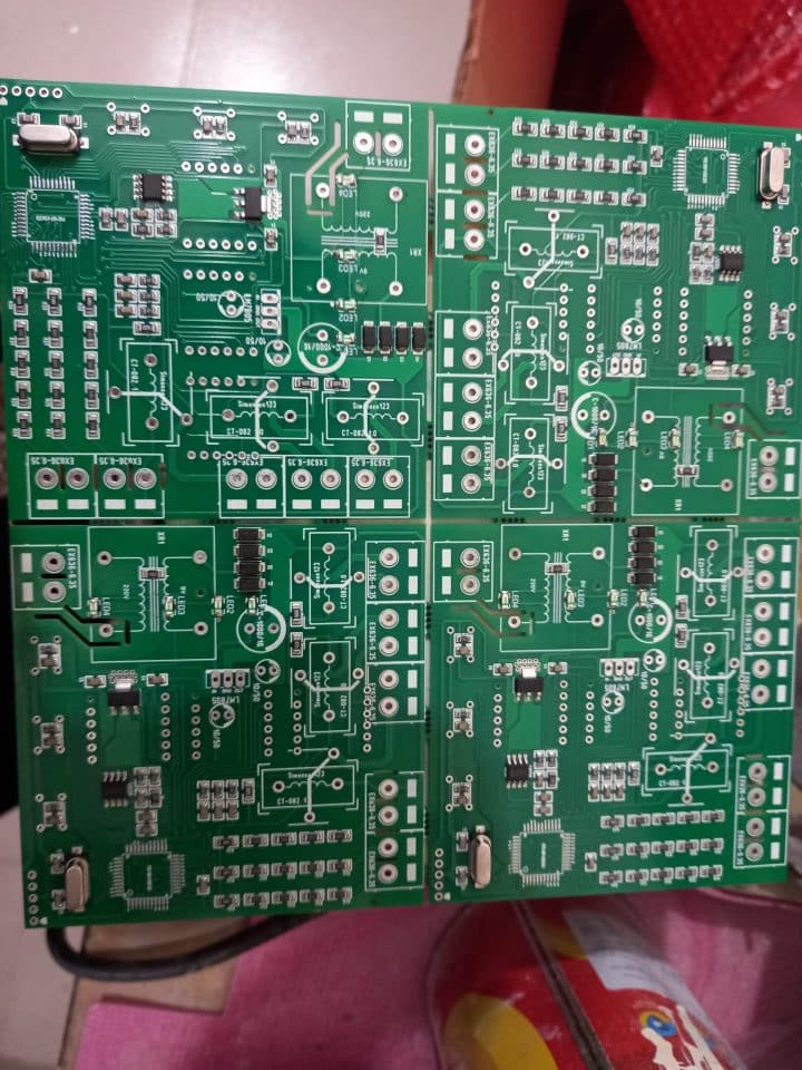
PCB:
Most of the time, I make PCBs for each project or product. Here is the PCB for our AC voltmeter using a PIC16F76 micro-controller and capacitor power supply. Note that I kept it multifunctional so that I can show how we can use the same design for different purposes. For this project, just follow the circuit diagram given above.


For professional designs like these feel free to chat with me through WhatsApp below.
Test result:
I used resistors that are 5% intolerant. Using 1% resistors will improve the measuring performance.
Conclusion:
This project was very simple and useful if you use it for good. By minor changes, this can be a good product too. I think this article will help you. Don’t forget to subscribe, more projects are coming soon. Thanks for reading.
Liked this article? Subscribe to our newsletter:
or,
Visit LabProjectsBD.com for more inspiring projects and tutorials.
Thank you!
Check this: 6V Lead-Acid battery Charger Circuits.


23 Comments
RK Hamy · 29/06/2021 at 3:58 am
Many Thanks for the excellent project.
As per my understanding…
you takes 1000 samples from AC waveform while finds maximum (adc) value in that 1000 numbers.
then you calculate rms voltage value of that maximum number. after collecting 60 RMS voltage samples You divide it by 60 to get average RMS AC Voltage.
Can you kindly explain the RMS calculation part
what is 137/100 or 1.37 (I cannot understand)
Again many thanks
MKDas · 29/06/2021 at 5:46 am
First it comes from voltage divier equation, Then 0.707 for peak to rms conversion. After that a calibration factor is multiplied with that. This is the one way. And the other way is to back engineering.
RK Hamy · 29/06/2021 at 8:03 am
Thank you so much for taking time to reply me.
When you have a free time, can you kindly explain following steps for me.
Voltage divider equation
Peak to RMS conversion
Calculate calibration factor
Really sorry if I am keep disturbing you,
I really love to learn how AC calculation done in this circuit.
MKDas · 29/06/2021 at 8:55 am
These are available in engineering books. Besides, Google can help you. These are very minor issues to explain.
Only one thing you may not understand is the calibration factor. This is very simple too. After putting all the mathematical values, you find that your meter is showing 210V while the actual reading is 215V. That means, your meter is reading 5 volts lower than the actual. This happens due to resistance tolerance. Now, what is your calibration factor? Simple, 215/210 = 1.0238 is your calibration factor. Now you need to multiply this with your previous value. I think it is clear to you now.
Thank you for understanding.
R K Hamy · 29/06/2021 at 9:09 am
Thank you so much for explaining thing.
max · 30/06/2021 at 12:15 am
thank you sir
where can i download the hex file
MKDas · 30/06/2021 at 4:50 am
Check again. I’ve uploaded the hex.
max · 01/07/2021 at 9:40 pm
thank you so much sir
enrique · 04/07/2021 at 3:06 pm
Thank you very much for sharing your knowledge, I follow all your publications, I am learning thanks to you
Greetings from Colombia
MKDas · 07/07/2021 at 5:09 am
Thanks.
R K Hamy · 04/08/2021 at 8:24 am
If possible Can you please publish an article and mikroC code of True RMS calculation.
MKDas · 04/08/2021 at 1:29 pm
Noted. I’ll try.
R K Hamy · 04/08/2021 at 6:29 pm
Thanks for the + response
Mihail · 02/07/2022 at 8:57 pm
I can’t understand how the circuit can work on the principle of a voltage divider on resistors without galvanic isolation. does the power supply of the same name make sense here? But what if the microcircuit is powered according to the usual scheme from a switching power supply, then will there be a potential difference between the voltage divider and the microcircuit itself and will it not burn out?
and even looking at this circuit, the question immediately arises, what if you add a shunt and start measuring the current also without galvanic isolation, what will this lead to? I opened a Chinese wattmeter and there the principle is the same as yours, but a shunt is also added
MKDas · 03/07/2022 at 11:10 am
#first tell me why you need galvanic isolation for voltage measurement?
#The primary purpose of this device is to show the voltage, with no user interface or anything else. So? better leave it along to measure and demonstrate the value on the display. Why do you need a canon to kill a mosquito?
#Any voltage over 5.6V to MCU, the pin will be burnt inside.
#Yes, we can introduce a shunt for current measurement, in fact, most of the wattmeters use it to reduce cost.
#yes, many meters use this simple principle, shunt? that is a matter of choice to measure current.
Mihail · 03/07/2022 at 2:19 pm
Hi! I’m all for your idea! The simpler, the better! Only I want to figure out why the microcontroller does not burn out now according to your scheme. We power it from a capacitor power supply, while we measure the phase voltage from a voltage divider (on the controller 5v, and on the voltage divider about 2.5v *, but there is a network frequency of 50hz, there is a phase voltage and 220v relative to zero). Why does the phase voltage not kill the controller if there is no galvanic isolation? I assume that the entire circuit (all elements) operates under phase voltage and because of this nothing burns out, and if you power the device from another source with galvanic isolation, it will burn out. Could you give me a link to read this information from some source, because I only come across capacitor power supplies.
MKDas · 03/07/2022 at 4:38 pm
I think, you never made any capacitor power supply before. That is why you are in confusion. If I’m correct, then I’ll suggest you try one before. That capacitor C1 and resistor R1 reduces the current to the regulator which is then limited by the Zener diode. And furthermore, there is a voltage regulator that is providing a 5V constant. So? MCU is not getting any high voltage at all.
And for that voltage divider, simply. 1K & 100K makes it possible to measure up to 500V RMS or 353V AC. And our line is 220V+/-. The resistor drops the voltage to the ADC pin. And for the reverse cycle, there is a protecting diode inside the MCU with ADC pin. That protected the reverse cycle. So, why the MCU will burn?
Mihail · 03/07/2022 at 6:58 pm
hmm, I completely trust you and understand the principle of operation of a capacitor power supply, looking at the datasheet on the MCU, I did not see a reverse diode on the diagrams (although theoretically it should be there at each input). Theoretically, this scheme can be applied to Atmega328p? And I understand that the resistors on the divider should be set to about 0.25 W, no less? Thanks for answers!
MKDas · 03/07/2022 at 7:07 pm
You should read the datasheet again Mr. Mihail. You can use the configuration for almost any microcontroller. Just read the datasheet carefully before you start with that. And I’ve been using this design for over 8yrs now. Many units (over 1000) are still being running in different devices/systems/home/panels. You can use it keeping your eyes closed. Thanks.
shafi · 27/05/2023 at 10:39 pm
plese pic16ff676 voltmeter hex code
PAUL · 27/04/2024 at 10:15 pm
GREETINGS
DO YOU HAVE A 3PHASE RESISTOR DIVIDER NETWORK CIRCUIT AVAILABLE
THANKING IN ADVANCE
MKDas · 01/05/2024 at 1:44 pm
no. use single phase configuration 3X
Imamul Ahmed · 02/07/2025 at 10:30 am
I need circuit diagram