Sometimes, you may need to make a DC/DC converter with minor components that can handle small loads. In this article, we are going to make something like that. This DC/DC converter using transistor has only a few components and can handle small loads or higher voltages, suitable to use with a small AA battery. So let’s start!
⚠️Disclaimer:
Working with electricity involves serious risk. Ensure you have the necessary skills and take proper safety precautions before attempting any electrical projects. Proceed at your own risk — the author assumes no responsibility for any damage, injury, or issues resulting from the use or misuse of the information provided.
All content on this website is original and protected by copyright. Please do not copy or reproduce content without permission. While most of the resources shared here are open-source and freely accessible for your learning and benefit, your respect for our intellectual effort is appreciated.
If you find our tutorials helpful, consider supporting us by purchasing related materials or sharing our work — it helps keep the content flowing.
Need help or have questions? Leave a comment below — the author is always happy to assist!
Table of Contents
When do you need this type of DC/DC converters?
When I was working on a project, I found that I need to drive a buzzer of 12V from a source of 3.7V LiPo. But the circuit should not be costly and should be as small as possible. After looking at similar circuits over the net, I found several circuits but only one was satisfactory. After little modification, that circuit becomes very useful to me. That is why I’m sharing this circuit so that you may get some help.
When you need to drive a small load such as a sensor, or a buzzer, or a relay with a battery of 1.5V, or such a source then you can use this type of DC/DC converters.
Circuit diagram:

Working principle:
This is actually an Astable multi-vibrator using Transistors. With a small change in its configuration, this DC/DC converter is designed. The Q1 & Q2 are the same transistors. Once the power is up, the Q2 starts switching until C1 gets charged. Once C1 is charged, Q1 triggers as there is no pull down to its base through R3 & C1. This turns Q2 off. Once Q2 is off, as C1 was charged, it triggers Q2 through R2 and R3. This process keeps going until power is sufficient.
PCB [if required]:

Test result:
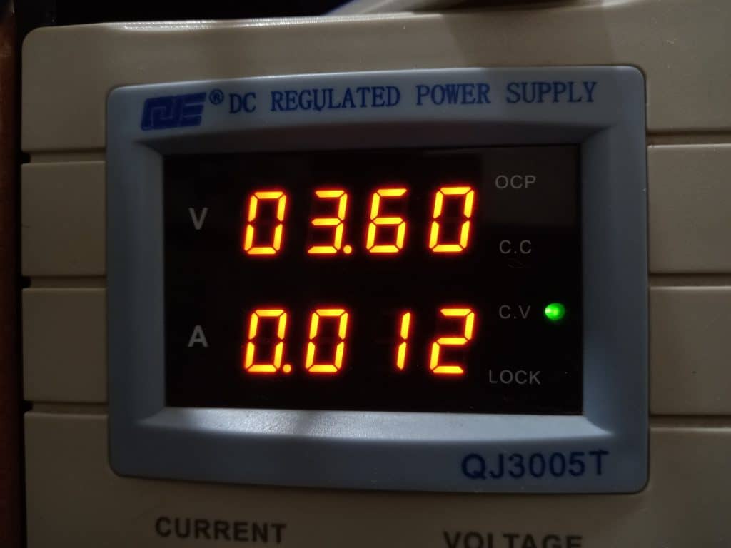
DC input 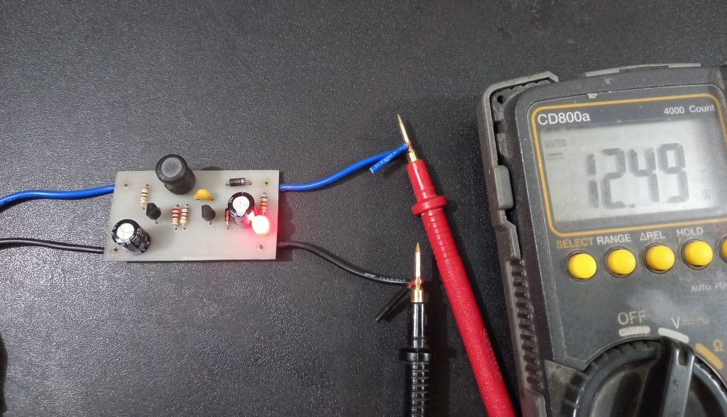
Output


Conclusion:
This article was a small one but can be helpful in the right situation. This dc dc converter circuit is only suitable for small loads driving from low voltage sources. So when you use this keep that in mind. Thanks.
Liked this article? Subscribe to our newsletter:
or,
Visit LabProjectsBD.com for more inspiring projects and tutorials.
Thank you!
You can check this article too: Simple Component Detector using PIC16F877A


4 Comments
Enrique · 22/10/2021 at 5:36 am
Excellent project like all his works. Thank you
To Moses · 05/10/2022 at 2:53 am
modify this circuit so as to comfortably carry a 3A load, what are we going change.
MKDas · 08/10/2022 at 12:39 pm
this is not suitable for high amp.
Bert · 12/04/2023 at 9:42 pm
The output voltage is not regulated. Adding feedback is possible with a resistor Ra from the output to the base of Q1 which is connected to ground via a resistor Rb. Vbe of Q1 is used as a reference voltage.
The idea is that when the output voltage is high enough, Q1 takes away the base current of Q2.
Here the input voltage, r1, r2 are also determining the output voltage. By leaving out R2 this can be avoided. Q1 base current is delevered via Ra.
I leave calculating the resistor values as an exercise for the reader.