Learn how to interface a stepper motor with an STM32 microcontroller using GPIO and PWM timers. This tutorial includes example code and step-by-step instructions for controlling the speed and direction of a stepper motor.
⚠️Disclaimer:
Working with electricity involves serious risk. Ensure you have the necessary skills and take proper safety precautions before attempting any electrical projects. Proceed at your own risk — the author assumes no responsibility for any damage, injury, or issues resulting from the use or misuse of the information provided.
All content on this website is original and protected by copyright. Please do not copy or reproduce content without permission. While most of the resources shared here are open-source and freely accessible for your learning and benefit, your respect for our intellectual effort is appreciated.
If you find our tutorials helpful, consider supporting us by purchasing related materials or sharing our work — it helps keep the content flowing.
Need help or have questions? Leave a comment below — the author is always happy to assist!
Table of Contents
Stepper Motors Introduction:
Stepper motors are DC brushless and synchronous motors. They rotate in discrete steps of predefined values and are able to rotate both clockwise and anticlockwise. Unlike other DC motors, they provide precise position control according to the number of steps per revolution for which the motor is designed. That means a complete revolution of a stepper motor is divided into a discrete number of steps. They are commonly used in CNC machines, Robotics, and 2D and 3D printers.
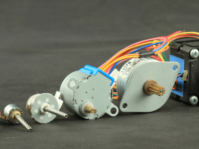
Types of Stepper motors:
There are 3 main types of stepper motors.
- Permanent magnet Stepper motors
- Variable Reluctance Stepper Motor
- Hybrid Stepper motors
Now, based on coil combination, two types of stepper motors are found.
- Unipolar Stepper motor and
- Bipolar Stepper motor.
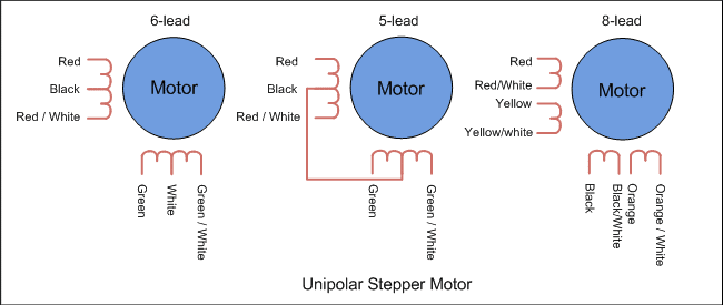
Unipolar Stepper motor:
This type of stepper motor has two coils per phase, and each coil can be energized separately using a unipolar power supply. The direction of the magnetic field generated by each coil can be reversed by switching the direction of the current flow. Unipolar stepper motors are relatively easy to control, but they have lower torque compared to bipolar stepper motors.
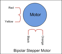
Bipolar Stepper Motor:
This type of stepper motor has one coil per phase, and each coil has a center tap that can be energized with a bipolar power supply. The direction of the magnetic field generated by each coil can be reversed by switching the polarity of the current flow. Bipolar stepper motors have higher torque compared to unipolar stepper motors, but they require a more complex control circuit
Interfacing Stepper Motor with STM32:
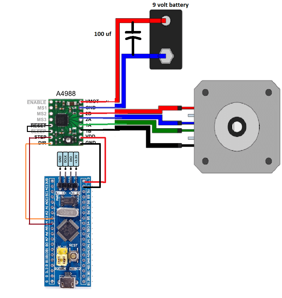
To interface a stepper motor with STM32, you can use a stepper motor drivers module such as the A4988 or DRV8825. These driver modules are designed to drive bipolar stepper motors and provide easy control over the motor’s speed and direction. Here are the steps to interface a stepper motor with STM32 using the A4988 driver module:
- Connect the stepper motor to the driver module. The stepper motor has four wires, which are typically color-coded. Connect the wires to the corresponding pins on the driver module.
- Connect the driver module to the STM32. The driver module has four pins for controlling the motor: STEP, DIR, ENABLE, and GND. Connect the STEP pin to a PWM output pin on the STM32, the DIR pin to a digital output pin on the STM32, and the ENABLE pin to another digital output pin on the STM32. Connect the GND pin to a ground pin on the STM32.
- Set up the GPIO pins on the STM32 for controlling the driver module. Configure the DIR and ENABLE pins as digital output pins and the PWM output pin as a PWM output pin using the STM32’s GPIO and Timer peripherals.
- Write code to control the stepper motor. To move the motor, you need to generate a series of pulses on the STEP pin. The number of pulses determines the speed of the motor, while the direction of the pulses determines the direction of the motor. To change the direction of the motor, set the DIR pin to either high or low.
A4988 Motor driver module:
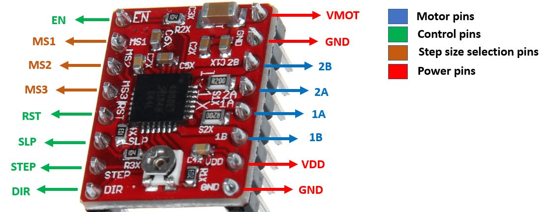
The A4988 is a motor driver module designed to control stepper motors. It is a popular and widely used driver module in the field of 3D printing, robotics, and CNC machines.
To know more about A4988 Check this link.
Circuit diagram:
Example Code:
Here is an example code snippet that demonstrates how to control a stepper motor using the A4988 driver module and STM32:
#include "stm32f4xx.h"

// Define GPIO pins for the stepper motor driver
#define STEP_PIN GPIO_Pin_8
#define DIR_PIN GPIO_Pin_9
#define ENABLE_PIN GPIO_Pin_10

// Define the timer used for PWM output
#define PWM_TIMER TIM2

// Define the frequency of the PWM signal
#define PWM_FREQ 1000

// Define the maximum speed of the stepper motor in steps per second
#define MAX_SPEED 200

// Define the acceleration of the stepper motor in steps per second squared
#define ACCELERATION 1000

// Define the number of steps per revolution of the stepper motor
#define STEPS_PER_REV 200

// Define the number of microsteps per step
#define MICROSTEPS 16

// Define the number of steps to move for each microstep
#define STEPS_PER_MICROSTEP (STEPS_PER_REV * MICROSTEPS)

// Define the maximum delay between steps in microseconds
#define MAX_STEP_DELAY (1000000 / MAX_SPEED)

// Define the minimum delay between steps in microseconds
#define MIN_STEP_DELAY (1000000 / (MAX_SPEED * ACCELERATION))

// Define the current step delay in microseconds
uint32_t step_delay = MAX_STEP_DELAY;

void GPIO_Init(void)
{
	GPIO_InitTypeDef GPIO_InitStruct;

	// Enable the GPIOA clock
	RCC_AHB1PeriphClockCmd(RCC_AHB1Periph_GPIOA, ENABLE);

	// Configure the STEP, DIR, and ENABLE pins as digital output pins
	GPIO_InitStruct.GPIO_Pin = STEP_PIN | DIR_PIN | ENABLE_PIN;
	GPIO_InitStruct.GPIO_Mode = GPIO_Mode_OUT;
	GPIO_InitStruct.GPIO_Speed = GPIO_Speed_50MHz;
	GPIO_InitStruct.GPIO_OType = GPIO_OType_PP;
	GPIO_InitStruct.GPIO_PuPd = GPIO_PuPd_NOPULL;
	GPIO_Init(GPIOA, &GPIO_InitStruct);
}

void PWM_Init(void)
{
	GPIO_InitTypeDef GPIO_InitStruct;
	TIM_TimeBaseInitTypeDef TIM_InitStruct;

	// Enable the GPIOA and TIM2 clocks
	RCC_AHB1PeriphClockCmd(RCC_AHB1Periph_GPIOA, ENABLE_PIN, ENABLE);
// Configure TIM2 CH1 (PA5) as PWM output
	GPIO_InitStruct.GPIO_Pin = GPIO_Pin_5;
	GPIO_InitStruct.GPIO_Mode = GPIO_Mode_AF;
	GPIO_InitStruct.GPIO_Speed = GPIO_Speed_50MHz;
	GPIO_InitStruct.GPIO_OType = GPIO_OType_PP;
	GPIO_InitStruct.GPIO_PuPd = GPIO_PuPd_NOPULL;
	GPIO_Init(GPIOA, &GPIO_InitStruct);

	GPIO_PinAFConfig(GPIOA, GPIO_PinSource5, GPIO_AF_TIM2);

// Configure TIM2 as a PWM timer
	TIM_InitStruct.TIM_Prescaler = SystemCoreClock / (PWM_FREQ * 65535) - 1;
	TIM_InitStruct.TIM_Period = 65535;
	TIM_InitStruct.TIM_CounterMode = TIM_CounterMode_Up;
	TIM_InitStruct.TIM_ClockDivision = TIM_CKD_DIV1;
	TIM_TimeBaseInit(PWM_TIMER, &TIM_InitStruct);

	TIM_OCInitTypeDef TIM_OC_InitStruct;

	TIM_OC_InitStruct.TIM_OCMode = TIM_OCMode_PWM1;
	TIM_OC_InitStruct.TIM_OutputState = TIM_OutputState_Enable;
	TIM_OC_InitStruct.TIM_OCPolarity = TIM_OCPolarity_High;
	TIM_OC_InitStruct.TIM_Pulse = 0;
	TIM_OC1Init(PWM_TIMER, &TIM_OC_InitStruct);

	TIM_Cmd(PWM_TIMER, ENABLE);
}

void delay_us(uint32_t us)
{
	TIM_Cmd(TIM6, DISABLE);
	TIM_SetCounter(TIM6, 0);
	TIM_SetAutoreload(TIM6, us - 1);
	TIM_Cmd(TIM6, ENABLE);
	while (TIM_GetCounter(TIM6) > 0)
		;
}
void step_motor(uint16_t steps, uint8_t dir)
{
// Set the DIR pin to the desired direction
	if (dir == 0)
	{
		GPIO_ResetBits(GPIOA, DIR_PIN);
	}
	else
	{
		GPIO_SetBits(GPIOA, DIR_PIN);
	}
// Generate the desired number of steps
	for (uint16_t i = 0; i < steps; i++)
	{
		// Generate a pulse on the STEP pin
		GPIO_SetBits(GPIOA, STEP_PIN);
		delay_us(step_delay);
		GPIO_ResetBits(GPIOA, STEP_PIN);
		delay_us(step_delay);
	}
}

int main(void)
{
// Initialize the GPIO and PWM peripherals
	GPIO_Init();
	PWM_Init();
// Enable the TIM6 clock for delay_us function
	RCC_APB1PeriphClockCmd(RCC_APB1Periph_TIM6, ENABLE);

// Disable the stepper motor driver
	GPIO_SetBits(GPIOA, ENABLE_PIN);

// Set the current step delay to the maximum delay
	step_delay = MAX_STEP_DELAY;

	while (1)
	{
		// Enable the stepper motor driver
		GPIO_ResetBits(GPIOA, ENABLE_PIN);

		// Move the motor in one direction for one revolution
		step_motor(STEPS_PER_REV * MICROSTEPS, 0);

		// Delay for 1 second
		delay_us(1000000);

		// Move the motor in the other direction for one revolution
		step_motor(STEPS_PER_REV * MICROSTEPS, 1);

		// Delay for 1 second
		delay_us(1000000);

		// Gradually increase the speed of the motor
		for (uint32_t delay = MAX_STEP_DELAY; delay > MIN_STEP_DELAY; delay -=
				ACCELERATION)
		{
			step_delay = delay;
			step_motor(STEPS_PER_MICROSTEP, 0);
		}

		// Gradually decrease the speed of the motor
		for (uint32_t delay = MIN_STEP_DELAY;

		delay < MAX_STEP_DELAY; delay += ACCELERATION)
		{
			step_delay = delay;
			step_motor(STEPS_PER_MICROSTEP, 1);
		}
		// Disable the stepper motor driver
		GPIO_SetBits(GPIOA, ENABLE_PIN);

		// Delay for 1 second
		delay_us(1000000);
	}
}
Code Explanation:
In this code, we first initialize the necessary peripherals, including the GPIO and PWM timers. We then define a delay_us function using a timer to generate accurate microsecond delays.
The step_motor function takes two arguments: the number of steps to take and the direction to move in (0 for forward, 1 for backward). It sets the DIR pin to the desired direction and generates the desired number of steps by pulsing the STEP pin with a delay specified by the current step_delay variable.
In the main function, we first enable the stepper motor driver by setting the ENABLE pin low. We then move the motor in one direction for one revolution, followed by a delay of one second, and then move the motor in the other direction for one revolution, followed by another delay of one second.
We then gradually increase and decrease the speed of the motor by adjusting the step_delay variable and calling the step_motor function repeatedly. Finally, we disable the stepper motor driver by setting the ENABLE pin high and delaying for one second before starting the loop again.
Conclusion:
Overall, this code provides a simple example of how to interface a stepper motor with an STM32 microcontroller using GPIO and PWM timers. It can be adapted to work with different stepper motors and motor drivers by adjusting the timing and pin assignments as necessary.
Read more on:
- How to interface a 16×2 LCD with an STM32
- How to interface ESP8266 with STM32
- How to interface DHT11 with STM32
- STM32 Development Boards: A Guide for Beginners
- How to interface the EM18 RFID module with STM32
Liked this article? Subscribe to our newsletter:
or,
Visit LabProjectsBD.com for more inspiring projects and tutorials.
Thank you!


2 Comments
Rajab · 11/07/2023 at 5:54 pm
how to start and stop multiple stepper motors at the same time irrespective of its steps in stm32..? like how the multistepper library works in arduino
MKDas · 15/07/2023 at 8:10 pm
look for your arduino code & examples of the library you are using. This is for STM32.