Learn how to interface the ESP8266 WiFi module with the STM32 microcontroller by reading our guide. Discover the steps involved in connecting the two devices, and access an example code to help you get started.
⚠️Disclaimer:
Working with electricity involves serious risk. Ensure you have the necessary skills and take proper safety precautions before attempting any electrical projects. Proceed at your own risk — the author assumes no responsibility for any damage, injury, or issues resulting from the use or misuse of the information provided.
All content on this website is original and protected by copyright. Please do not copy or reproduce content without permission. While most of the resources shared here are open-source and freely accessible for your learning and benefit, your respect for our intellectual effort is appreciated.
If you find our tutorials helpful, consider supporting us by purchasing related materials or sharing our work — it helps keep the content flowing.
Need help or have questions? Leave a comment below — the author is always happy to assist!
Table of Contents
About STM32:
STM32 is a family of microcontrollers that are widely used in embedded systems, offering a range of powerful features such as low power consumption, high performance, and a rich set of peripherals. One of the most useful peripherals in STM32 microcontrollers is the WiFi module, which provides wireless communication capabilities to a device. In this article, we will discuss STM32 WiFi communication and how it can be used to build wireless applications.
About WiFi modules:
WiFi communication is a wireless communication technology that uses radio waves to transmit and receive data over a local area network (LAN). It is a widely used technology for wireless communication and is supported by most modern electronic devices. WiFi communication is based on the IEEE 802.11 standard, which defines the physical and data link layers of the protocol.
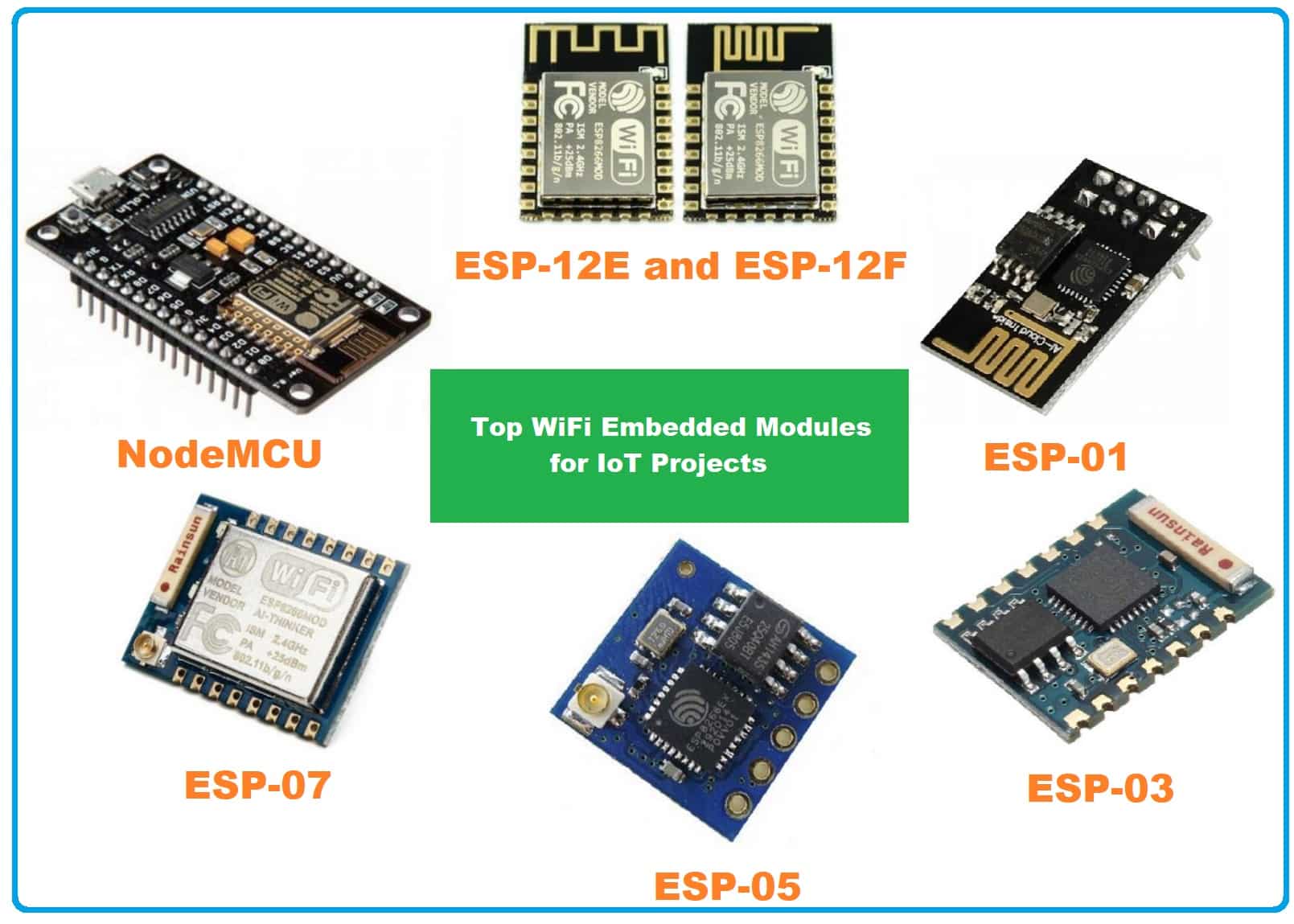
Among these, the ESP8266 is the most popular which is also known as ESP-01.
Interfacing ESP8266 with STM32:
The ESP8266 is a popular WiFi module that can be easily integrated with an STM32 microcontroller to add wireless connectivity to your embedded system. Here are the steps to interface the ESP8266 with an STM32 microcontroller:
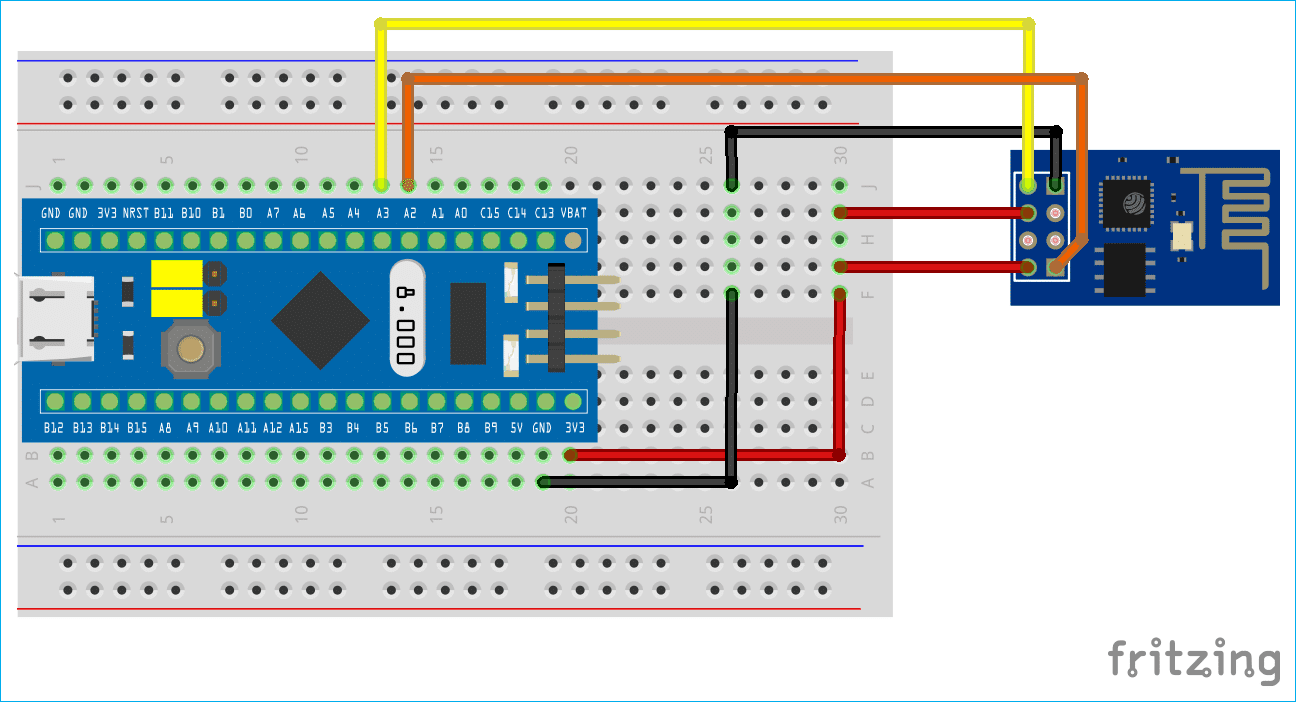
- Hardware connections: The first step is to connect the ESP8266 module to the STM32 microcontroller. The ESP8266 module can be connected to the STM32 microcontroller through a serial interface, such as UART or SPI. The specific pins used for the serial interface will depend on the STM32 microcontroller board you are using, so be sure to consult the board’s datasheet for details.
- Software setup: Once the hardware connections are in place, you will need to set up the software to interface with the ESP8266 module. You can use the STM32 software development kit (SDK) to configure and control the ESP8266 module. The SDK provides a range of functions for configuring the ESP8266 module, such as setting the wireless protocol, configuring the wireless network, and sending and receiving data over the network.
- Initialize the ESP8266 module: Before using the ESP8266 module, you will need to initialize it by sending it some basic commands. You can do this by sending AT commands over the serial interface to the ESP8266 module. These commands will configure the module to work with your wireless network and establish a connection to the internet.
- Send and receive data: Once the ESP8266 module is initialized, you can start sending and receiving data over the wireless network. You can use the SDK to send and receive data packets over the network, and the ESP8266 module will handle the wireless communication.
- Debugging: If you encounter any issues with the ESP8266 module, you can use the debug output from the module to troubleshoot the issue. The ESP8266 module provides debug output over the serial interface, which can be viewed using a terminal emulator or similar tool.
In summary, interfacing the ESP8266 with an STM32 microcontroller is a relatively simple process that can be accomplished with just a few hardware connections and some software setup. By adding wireless connectivity to your embedded system, you can build a range of wireless applications that can be deployed in a wide range of industries and applications.
Example code:
Here’s an example code on how to interface ESP8266 with STM32 using the STM32 HAL (Hardware Abstraction Layer) library:
#include "stm32f4xx_hal.h"
#include <string.h>

UART_HandleTypeDef huart2;

void SystemClock_Config(void);
static void MX_GPIO_Init(void);
static void MX_USART2_UART_Init(void);

void ESP8266_Init(void) {
  char buffer[50];
  HAL_UART_Transmit(&huart2, (uint8_t*)"AT+RST\r\n", strlen("AT+RST\r\n"), 1000);
  HAL_Delay(2000);
  HAL_UART_Transmit(&huart2, (uint8_t*)"AT+CWMODE=1\r\n", strlen("AT+CWMODE=1\r\n"), 1000);
  HAL_Delay(2000);
  sprintf(buffer, "AT+CWJAP=\"SSID\",\"password\"\r\n");
  HAL_UART_Transmit(&huart2, (uint8_t*)buffer, strlen(buffer), 1000);
  HAL_Delay(2000);
}

void ESP8266_SendData(char* data) {
  char buffer[50];
  sprintf(buffer, "AT+CIPSEND=%d\r\n", strlen(data));
  HAL_UART_Transmit(&huart2, (uint8_t*)buffer, strlen(buffer), 1000);
  HAL_Delay(1000);
  HAL_UART_Transmit(&huart2, (uint8_t*)data, strlen(data), 1000);
  HAL_Delay(1000);
}

int main(void) {
  HAL_Init();
  SystemClock_Config();
  MX_GPIO_Init();
  MX_USART2_UART_Init();

  ESP8266_Init();

  while (1) {
    ESP8266_SendData("Hello World!");
    HAL_Delay(5000);
  }
}

void SystemClock_Config(void) {
  RCC_OscInitTypeDef RCC_OscInitStruct = {0};
  RCC_ClkInitTypeDef RCC_ClkInitStruct = {0};
  RCC_PeriphCLKInitTypeDef PeriphClkInit = {0};

  /** Configure the main internal regulator output voltage
  */
  __HAL_RCC_PWR_CLK_ENABLE();
  __HAL_PWR_VOLTAGESCALING_CONFIG(PWR_REGULATOR_VOLTAGE_SCALE1);
  /** Initializes the CPU, AHB and APB busses clocks
  */
  RCC_OscInitStruct.OscillatorType = RCC_OSCILLATORTYPE_HSI;
  RCC_OscInitStruct.HSIState = RCC_HSI_ON;
  RCC_OscInitStruct.HSICalibrationValue = RCC_HSICALIBRATION_DEFAULT;
  RCC_OscInitStruct.PLL.PLLState = RCC_PLL_NONE;
  if (HAL_RCC_OscConfig(&RCC_OscInitStruct) != HAL_OK) {
    Error_Handler();
  }
  /** Initializes the CPU, AHB and APB busses clocks
  */
  RCC_ClkInitStruct.ClockType = RCC_CLOCKTYPE_HCLK|RCC_CLOCKTYPE_SYSCLK
                              |RCC_CLOCKTYPE_PCLK1|RCC_CLOCKTYPE_PCLK2;
  RCC_ClkInitStruct.SYSCLKSource = RCC_SYSCLKSOURCE_HSI;
  RCC_ClkInitStruct.AHBCLKDivider = RCC_SYSCLK_DIV1;
  RCC_ClkInitStruct.APB1CLKDivider = RCC_HCLK_DIV1;
  RCC_ClkInitStruct.APB2CLKDivider = RCC_HCLK_DIV1;

  if (HAL_RCC_ClockConfig(&RCC_ClkInitStruct, FLASH_LATENCY_0) != HAL_OK) {
    Error_Handler();
  }
  PeriphClkInit.PeriphClockSelection = RCC_PERIPHCLK_USART2;
  PeriphClkInit.Usart2ClockSelection = RCC_USART2CLKSOURCE_PCLK1;
  if (HAL_RCCEx_PeriphCLKConfig
&PeriphClkInit) != HAL_OK) {
Error_Handler();
}
}

static void MX_USART2_UART_Init(void) {
huart2.Instance = USART2;
huart2.Init.BaudRate = 115200;
huart2.Init.WordLength = UART_WORDLENGTH_8B;
huart2.Init.StopBits = UART_STOPBITS_1;
huart2.Init.Parity = UART_PARITY_NONE;
huart2.Init.Mode = UART_MODE_TX_RX;
huart2.Init.HwFlowCtl = UART_HWCONTROL_NONE;
huart2.Init.OverSampling = UART_OVERSAMPLING_16;
if (HAL_UART_Init(&huart2) != HAL_OK) {
Error_Handler();
}
}

static void MX_GPIO_Init(void) {
GPIO_InitTypeDef GPIO_InitStruct = {0};

/* GPIO Ports Clock Enable */
__HAL_RCC_GPIOA_CLK_ENABLE();

/*Configure GPIO pin : PA0 */
GPIO_InitStruct.Pin = GPIO_PIN_0;
GPIO_InitStruct.Mode = GPIO_MODE_INPUT;
GPIO_InitStruct.Pull = GPIO_NOPULL;
HAL_GPIO_Init(GPIOA, &GPIO_InitStruct);
}

void Error_Handler(void) {
__disable_irq();
while (1) {
}
}

#ifdef USE_FULL_ASSERT
void assert_failed(uint8_t file, uint32_t line) {
}
#endif / USE_FULL_ASSERT */
In this example, we have implemented two functions for interfacing with the ESP8266 module: ESP8266_Init() and ESP8266_SendData(). The ESP8266_Init() function initializes the ESP8266 module by resetting it, setting it to Station mode, and connecting it to a WiFi network. The ESP8266_SendData() the function sends a string of data to the module.
The main function initializes the system clock, GPIO pins, and UART for communication. It then calls the ESP8266_Init() function to initialize the module, and sends the string “Hello World!” to the module every 5 seconds using the ESP8266_SendData() function.
Note: Note that this is just an example code and it might require modifications to work properly with your specific setup and requirements.
To use this code, you will need to make sure that you have connected the ESP8266 module to the STM32 microcontroller correctly. The ESP8266 module should be connected to the UART interface of the STM32, with the TX pin of the module connected to the RX pin of the STM32, and the RX pin of the module connected to the TX pin of the STM32.
You will also need to modify the code to match the SSID and password of the WiFi network you want to connect to. You can do this by modifying the ssid and password variables in the ESP8266_Init() function.
Once you have made the necessary modifications to the code, you can compile and upload it to your STM32 microcontroller using your preferred IDE or toolchain.
Conclusion:
In conclusion, interfacing the ESP8266 module with the STM32 microcontroller can enable you to add WiFi connectivity to your projects. With the example code provided, you can get started with implementing this interface in your own projects.
Read more on:
- How to interface DHT11 with STM32
- Designing a BMS with STM32
- STM32 Bluetooth Low Energy & its application
- STM32 Development Boards: A Guide for Beginners
- How to interface the EM18 RFID module with STM32
Liked this article? Subscribe to our newsletter:
or,
Visit LabProjectsBD.com for more inspiring projects and tutorials.
Thank you!


4 Comments
Dewo · 11/06/2023 at 10:48 pm
How to debug ESP8266 with HAL lib ?
MKDas · 14/06/2023 at 12:00 pm
may be not possible.
Karlsson · 10/07/2023 at 1:57 am
Hello!
Is it possible to build ESP8266 device without STM32 or external mictrocontroller is always needed for ESP8266 or ESP32-S?
MKDas · 15/07/2023 at 8:11 pm
not impossible