In this article, we will learn ADC Reading with STM32 BluePill or other STM32 ICs. We are using CubeMx IDE and here is how we can configure the code for this purpose.
⚠️Disclaimer:
Working with electricity involves serious risk. Ensure you have the necessary skills and take proper safety precautions before attempting any electrical projects. Proceed at your own risk — the author assumes no responsibility for any damage, injury, or issues resulting from the use or misuse of the information provided.
All content on this website is original and protected by copyright. Please do not copy or reproduce content without permission. While most of the resources shared here are open-source and freely accessible for your learning and benefit, your respect for our intellectual effort is appreciated.
If you find our tutorials helpful, consider supporting us by purchasing related materials or sharing our work — it helps keep the content flowing.
Need help or have questions? Leave a comment below — the author is always happy to assist!
Table of Contents
Why do you need ADC?
ADC is one of the fundamental features of microcontrollers. ADC helps read analog signals or voltage, and then we can get a digital value of that signal or voltage. From IC to IC, ADC configuration carries a bit. Such as 8bit, 10 bit, 12bit 24bit, 32bit etc. In STM32, you have multiple bits of ADCs in most cases. So, when you are using any microcontroller, check the datasheet before configuring the ADC.
Start making the project:
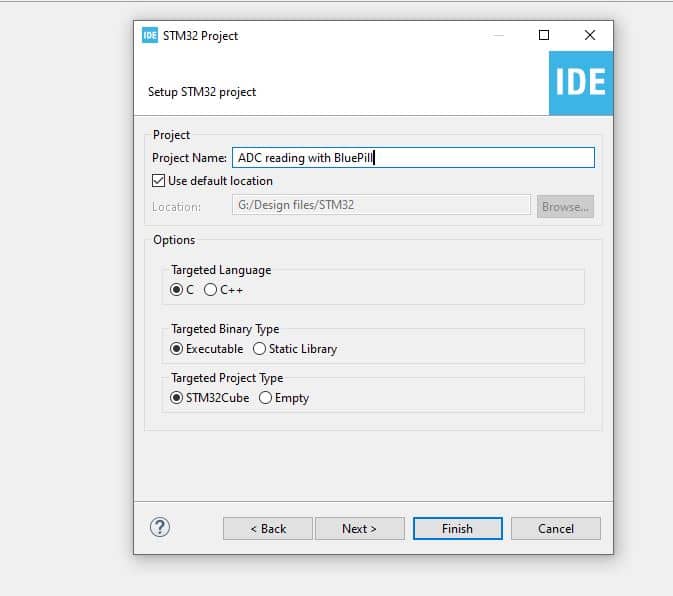
Step#1: Create the name after opening a new project.
Step#2: Configure SYS and RCC:
In SYS or the system, select the Serial wire as the Debugger. and Timebase source to any timer.
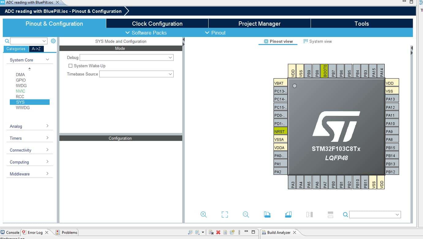
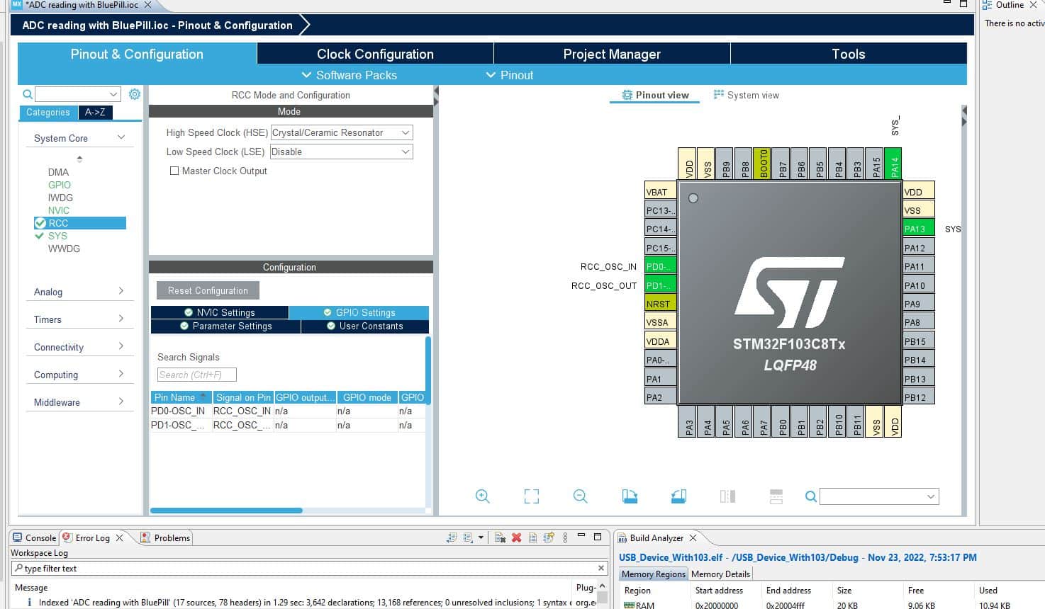
Then configure the RCC, and select Crystal Ceramic Resonator.
Step#3: Configure ADC.
Now, you need to configure the ADC. You can do it from the left side selection or by clicking the pins.
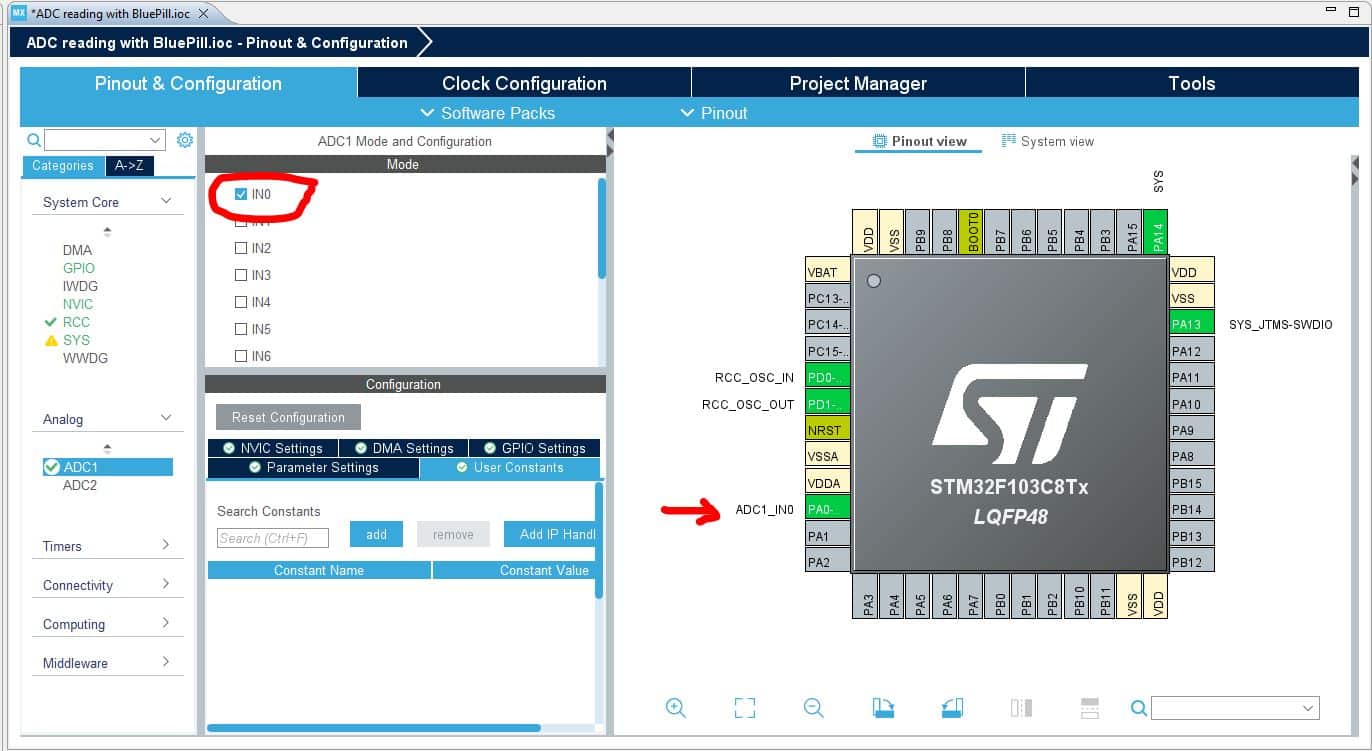
Here, you can use any channel you need.
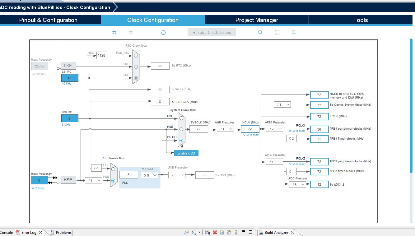
Step#4: Setup Clock
Now, you need to set up the clock. As I’m using a blue pill module here, so I’ll select 8MHz which is the default here.
Now, click on save to generate the code. And the compiler will generate a code for you. and you need some lines to add here.
Main.c file:
/* USER CODE BEGIN Header */
/**
  ******************************************************************************
  * @file           : main.c
  * @brief          : Main program body
  ******************************************************************************
  * @attention
  *
  * Copyright (c) 2022 STMicroelectronics.
  * All rights reserved.
  *
  * This software is licensed under terms that can be found in the LICENSE file
  * in the root directory of this software component.
  * If no LICENSE file comes with this software, it is provided AS-IS.
  *
  ******************************************************************************
  */
/* USER CODE END Header */
/* Includes ------------------------------------------------------------------*/
#include "main.h"

/* Private includes ----------------------------------------------------------*/
/* USER CODE BEGIN Includes */

/* USER CODE END Includes */

/* Private typedef -----------------------------------------------------------*/
/* USER CODE BEGIN PTD */

/* USER CODE END PTD */

/* Private define ------------------------------------------------------------*/
/* USER CODE BEGIN PD */
/* USER CODE END PD */

/* Private macro -------------------------------------------------------------*/
/* USER CODE BEGIN PM */

/* USER CODE END PM */

/* Private variables ---------------------------------------------------------*/
ADC_HandleTypeDef hadc1;

/* USER CODE BEGIN PV */

/* USER CODE END PV */

/* Private function prototypes -----------------------------------------------*/
void SystemClock_Config(void);
static void MX_GPIO_Init(void);
static void MX_ADC1_Init(void);
/* USER CODE BEGIN PFP */

/* USER CODE END PFP */

/* Private user code ---------------------------------------------------------*/
/* USER CODE BEGIN 0 */
uint16_t adc_result=0;
/* USER CODE END 0 */

/**
  * @brief  The application entry point.
  * @retval int
  */
int main(void)
{
  /* USER CODE BEGIN 1 */

  /* USER CODE END 1 */

  /* MCU Configuration--------------------------------------------------------*/

  /* Reset of all peripherals, Initializes the Flash interface and the Systick. */
  HAL_Init();

  /* USER CODE BEGIN Init */

  /* USER CODE END Init */

  /* Configure the system clock */
  SystemClock_Config();

  /* USER CODE BEGIN SysInit */

  /* USER CODE END SysInit */

  /* Initialize all configured peripherals */
  MX_GPIO_Init();
  MX_ADC1_Init();
  /* USER CODE BEGIN 2 */
  HAL_ADC_Start(&hadc1);
  /* USER CODE END 2 */

  /* Infinite loop */
  /* USER CODE BEGIN WHILE */
  while (1)
  {
    /* USER CODE END WHILE */

    /* USER CODE BEGIN 3 */
	  HAL_ADC_PollForConversion(&hadc1,1000);
	  adc_result = HAL_ADC_GetValue(&hadc1);
  }
  /* USER CODE END 3 */
}

/**
  * @brief System Clock Configuration
  * @retval None
  */
void SystemClock_Config(void)
{
  RCC_OscInitTypeDef RCC_OscInitStruct = {0};
  RCC_ClkInitTypeDef RCC_ClkInitStruct = {0};
  RCC_PeriphCLKInitTypeDef PeriphClkInit = {0};

  /** Initializes the RCC Oscillators according to the specified parameters
  * in the RCC_OscInitTypeDef structure.
  */
  RCC_OscInitStruct.OscillatorType = RCC_OSCILLATORTYPE_HSE;
  RCC_OscInitStruct.HSEState = RCC_HSE_ON;
  RCC_OscInitStruct.HSEPredivValue = RCC_HSE_PREDIV_DIV1;
  RCC_OscInitStruct.HSIState = RCC_HSI_ON;
  RCC_OscInitStruct.PLL.PLLState = RCC_PLL_ON;
  RCC_OscInitStruct.PLL.PLLSource = RCC_PLLSOURCE_HSE;
  RCC_OscInitStruct.PLL.PLLMUL = RCC_PLL_MUL9;
  if (HAL_RCC_OscConfig(&RCC_OscInitStruct) != HAL_OK)
  {
    Error_Handler();
  }

  /** Initializes the CPU, AHB and APB buses clocks
  */
  RCC_ClkInitStruct.ClockType = RCC_CLOCKTYPE_HCLK|RCC_CLOCKTYPE_SYSCLK
                              |RCC_CLOCKTYPE_PCLK1|RCC_CLOCKTYPE_PCLK2;
  RCC_ClkInitStruct.SYSCLKSource = RCC_SYSCLKSOURCE_PLLCLK;
  RCC_ClkInitStruct.AHBCLKDivider = RCC_SYSCLK_DIV1;
  RCC_ClkInitStruct.APB1CLKDivider = RCC_HCLK_DIV2;
  RCC_ClkInitStruct.APB2CLKDivider = RCC_HCLK_DIV1;

  if (HAL_RCC_ClockConfig(&RCC_ClkInitStruct, FLASH_LATENCY_2) != HAL_OK)
  {
    Error_Handler();
  }
  PeriphClkInit.PeriphClockSelection = RCC_PERIPHCLK_ADC;
  PeriphClkInit.AdcClockSelection = RCC_ADCPCLK2_DIV6;
  if (HAL_RCCEx_PeriphCLKConfig(&PeriphClkInit) != HAL_OK)
  {
    Error_Handler();
  }
}

/**
  * @brief ADC1 Initialization Function
  * @param None
  * @retval None
  */
static void MX_ADC1_Init(void)
{

  /* USER CODE BEGIN ADC1_Init 0 */

  /* USER CODE END ADC1_Init 0 */

  ADC_ChannelConfTypeDef sConfig = {0};

  /* USER CODE BEGIN ADC1_Init 1 */

  /* USER CODE END ADC1_Init 1 */

  /** Common config
  */
  hadc1.Instance = ADC1;
  hadc1.Init.ScanConvMode = ADC_SCAN_DISABLE;
  hadc1.Init.ContinuousConvMode = ENABLE;
  hadc1.Init.DiscontinuousConvMode = DISABLE;
  hadc1.Init.ExternalTrigConv = ADC_SOFTWARE_START;
  hadc1.Init.DataAlign = ADC_DATAALIGN_RIGHT;
  hadc1.Init.NbrOfConversion = 1;
  if (HAL_ADC_Init(&hadc1) != HAL_OK)
  {
    Error_Handler();
  }

  /** Configure Regular Channel
  */
  sConfig.Channel = ADC_CHANNEL_0;
  sConfig.Rank = ADC_REGULAR_RANK_1;
  sConfig.SamplingTime = ADC_SAMPLETIME_1CYCLE_5;
  if (HAL_ADC_ConfigChannel(&hadc1, &sConfig) != HAL_OK)
  {
    Error_Handler();
  }
  /* USER CODE BEGIN ADC1_Init 2 */

  /* USER CODE END ADC1_Init 2 */

}

/**
  * @brief GPIO Initialization Function
  * @param None
  * @retval None
  */
static void MX_GPIO_Init(void)
{

  /* GPIO Ports Clock Enable */
  __HAL_RCC_GPIOD_CLK_ENABLE();
  __HAL_RCC_GPIOA_CLK_ENABLE();

}

/* USER CODE BEGIN 4 */

/* USER CODE END 4 */

/**
  * @brief  Period elapsed callback in non blocking mode
  * @note   This function is called  when TIM3 interrupt took place, inside
  * HAL_TIM_IRQHandler(). It makes a direct call to HAL_IncTick() to increment
  * a global variable "uwTick" used as application time base.
  * @param  htim : TIM handle
  * @retval None
  */
void HAL_TIM_PeriodElapsedCallback(TIM_HandleTypeDef *htim)
{
  /* USER CODE BEGIN Callback 0 */

  /* USER CODE END Callback 0 */
  if (htim->Instance == TIM3) {
    HAL_IncTick();
  }
  /* USER CODE BEGIN Callback 1 */

  /* USER CODE END Callback 1 */
}

/**
  * @brief  This function is executed in case of error occurrence.
  * @retval None
  */
void Error_Handler(void)
{
  /* USER CODE BEGIN Error_Handler_Debug */
  /* User can add his own implementation to report the HAL error return state */
  __disable_irq();
  while (1)
  {
  }
  /* USER CODE END Error_Handler_Debug */
}

#ifdef  USE_FULL_ASSERT
/**
  * @brief  Reports the name of the source file and the source line number
  *         where the assert_param error has occurred.
  * @param  file: pointer to the source file name
  * @param  line: assert_param error line source number
  * @retval None
  */
void assert_failed(uint8_t *file, uint32_t line)
{
  /* USER CODE BEGIN 6 */
  /* User can add his own implementation to report the file name and line number,
     ex: printf("Wrong parameters value: file %s on line %d\r\n", file, line) */
  /* USER CODE END 6 */
}
#endif /* USE_FULL_ASSERT */
You need to add only 4 lines of code here. In the variable section on the top, simply declare the variable. And inside main, start the ADC, and then in the while loop, simply read the value.
Here, HAL_ADC_PollForConversion(&hadc1,1000); line sets in what time interval the MCU will poll for a conversion. I used 1000mS of time here, you can use your own.
And the next line, I simply take the reading to adc_result variable.
Debugging:
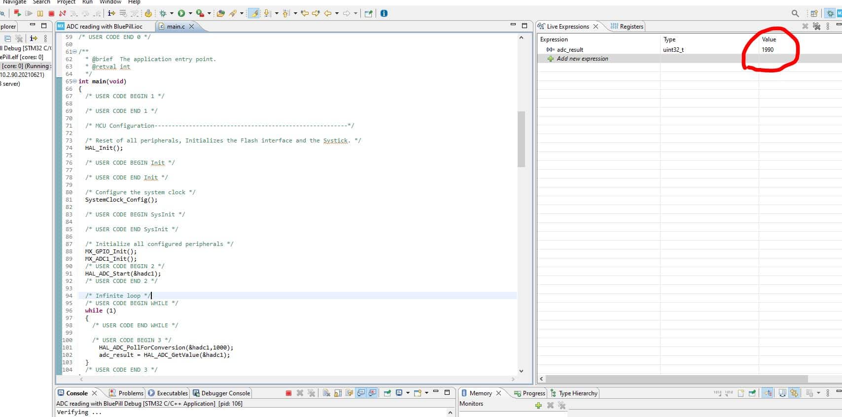
Now, one of the most useful features of CubeMx is debugging can help you read the value directly.
Simply click on debug and let the IDE to set. Then click run or press F8.
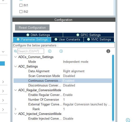
You may not find any value in the live Expression yet. Because the default setting of ADC will read only one sample which we can’t read continuously. So, stop debugging and go back to ADC setting from .ioc file.
Then, simply enable Continuous Conversion.
Now, you can read the value.
I hope this simple article will help you learning STM32. See you soon in the next article.
You can read my other articles on STM32:
Liked this article? Subscribe to our newsletter:
or,
Visit LabProjectsBD.com for more inspiring projects and tutorials.
Thank you!


0 Comments