A monitoring and control display for an industrial three-phase battery charger, designed and built for a charger manufacturer. It replaces a panel of separate meters and indicator lamps with one 7-inch touch screen that shows the whole power path live, raises faults with an audible alarm, and lets the service engineer set up and calibrate the charger on site.
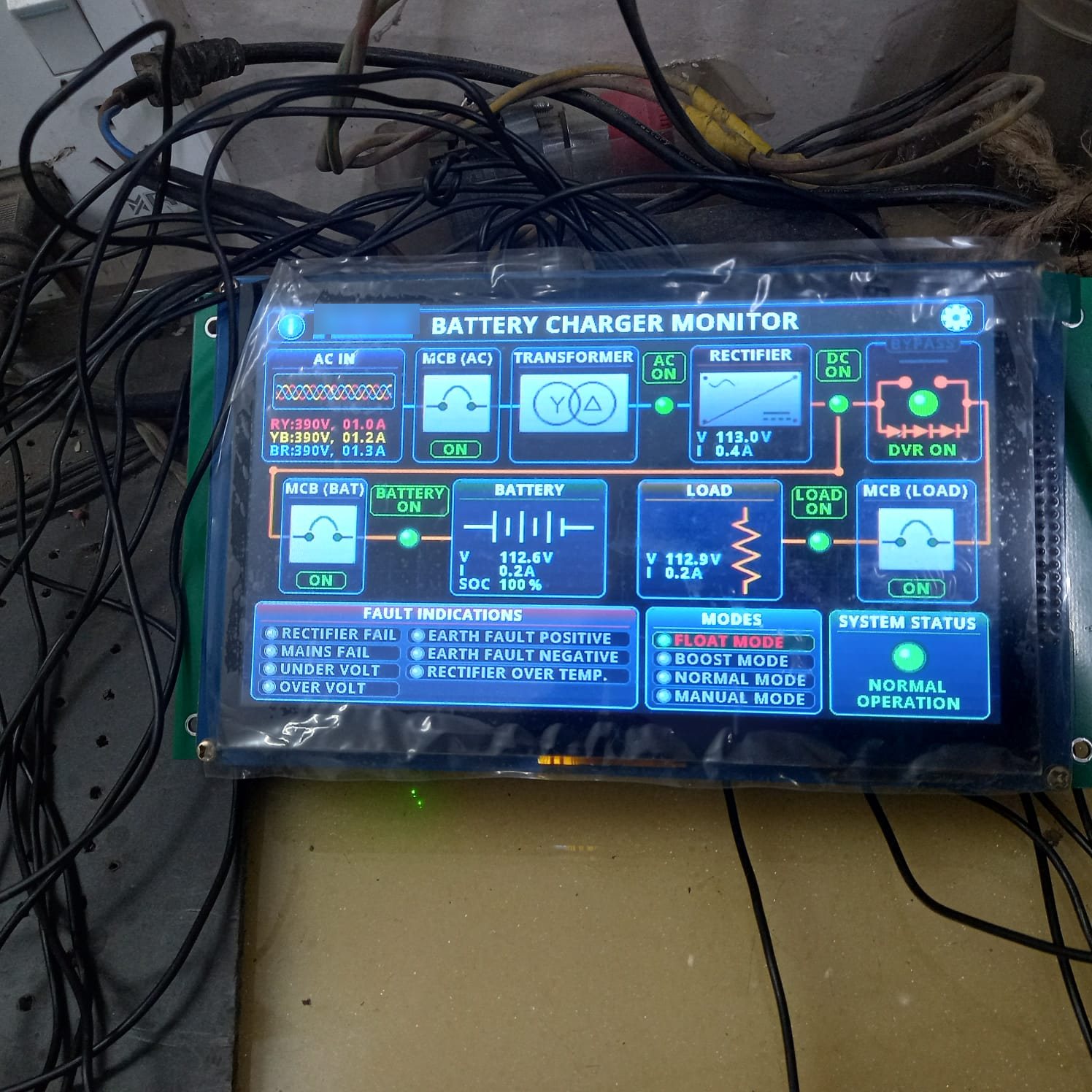
Table of Contents
What the operator sees
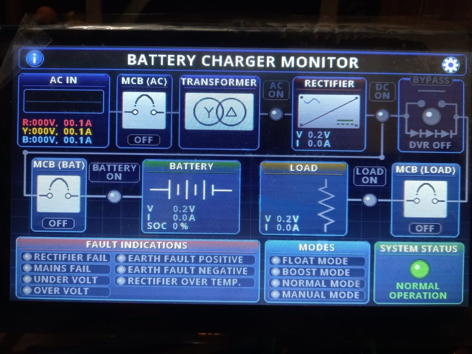
The home screen is a live single-line diagram: AC input, AC breaker, transformer, rectifier, battery branch, DC bypass and load branch. Connecting lines glow when power flows and turn grey when a section is off, so the state of the charger is clear at a glance.
- Three-phase input: line-to-line voltages (RY, YB, BR) and line currents; a failed phase is flagged as PHASE x FAILED (good phase = 180–250 V to neutral)
- Rectifier output voltage and current (battery current + load current)
- Battery voltage, current and state of charge
- Load voltage and current
- Breaker status for AC, battery and load, and DC bypass (DVR) state
- Operating mode: float, boost, auto or manual
- Faults: rectifier fail, mains fail, under-voltage, over-voltage, earth fault positive/negative, rectifier over-temperature
Alarms
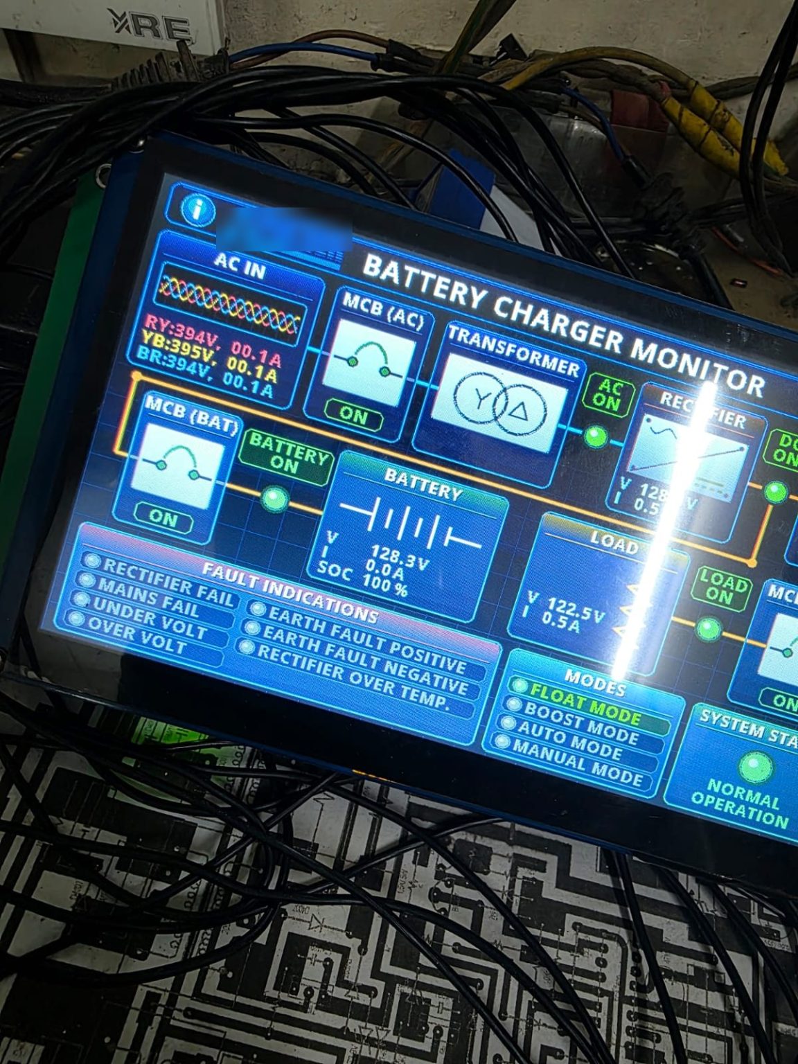
- Any active fault turns its indicator red and starts the buzzer
- Tapping SYSTEM STATUS silences the buzzer until the faults clear or 30 minutes pass; a new fault restarts it
- Faults are live: they clear automatically when the input condition returns to normal
Setup and calibration
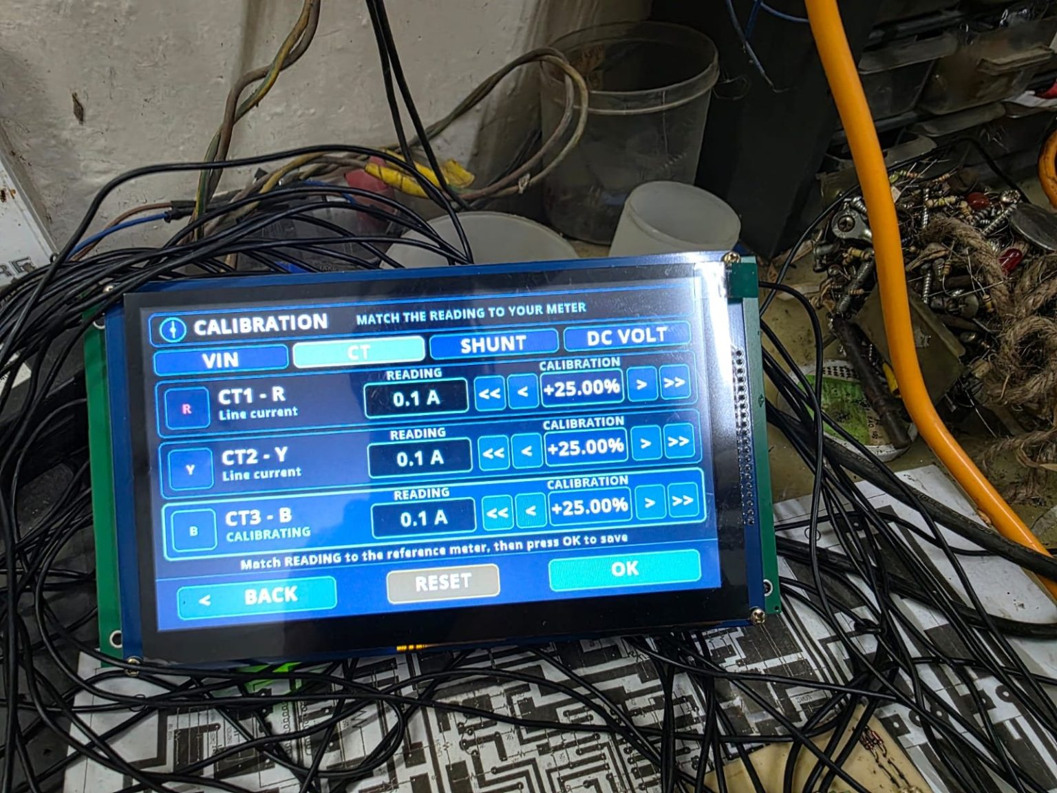
A settings page sets the battery nominal voltage, the external CT ratio and the shunt ratings. A protected calibration page, opened only by a deliberate tap sequence, lets the engineer match every analog channel to a reference meter within ±25%. All settings and calibration values are stored in FRAM and survive power cycles.
Hardware and measurement
| Item | Detail |
|---|---|
| Display | 7-inch 800×480 TFT, SSD1963 controller, resistive touch |
| Controller | 32-bit microcontroller with DMA-driven ADC sampling |
| AC voltage | Per-phase potential transformers (220:12) |
| AC current | External X:5 A CTs (for example 200:5) into on-board 5 A:5 mA CTs with burden resistors |
| DC current | Selectable shunts (for example 10 A or 100 A at 75 mV) |
| DC voltage | High-value dividers for battery, rectifier output and load; typical 96–130 V systems |
| Storage | FRAM for settings, CT/shunt ratings and calibration |
| Variants | Single-phase and three-phase input models |
Result
The display was bench-tested on a live three-phase charger in float mode with load connected, including bypass operation on AC failure. One controller covers both single-phase and three-phase charger models, configured from the settings page instead of separate firmware builds.
Need something similar?
We design monitoring and control electronics for chargers, inverters and other power equipment, from the measurement front end to the touch interface. Message us on WhatsApp or use the contact form.



0 Comments