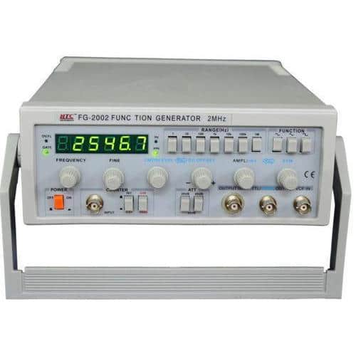
In this article, we will learn to make a function generator using ICL8038 IC. A function generator is a very useful device for anyone who works with electronics. Sine wave, Triangular wave, Square wave are the basic wave shapes we all need in electronics work.
⚠️Disclaimer:
Working with electricity involves serious risk. Ensure you have the necessary skills and take proper safety precautions before attempting any electrical projects. Proceed at your own risk — the author assumes no responsibility for any damage, injury, or issues resulting from the use or misuse of the information provided.
All content on this website is original and protected by copyright. Please do not copy or reproduce content without permission. While most of the resources shared here are open-source and freely accessible for your learning and benefit, your respect for our intellectual effort is appreciated.
If you find our tutorials helpful, consider supporting us by purchasing related materials or sharing our work — it helps keep the content flowing.
Need help or have questions? Leave a comment below — the author is always happy to assist!
Table of Contents
What is function generator:
A function generator is usually a piece of electronic test equipment or software used to generate different types of electrical waveforms over a wide range of frequencies. Some of the most common waveforms produced by the function generator are the sine wave, square wave, triangular wave, and sawtooth shapes. These waveforms can be either repetitive or single-shot (which requires an internal or external trigger source). Integrated circuits used to generate waveforms may also be described as function generator ICs.
About ICL8038:
ICL8038 is a waveform generator. Here is the functional block diagram of this IC.

Other similar IC:
Yes, there are similar ICs that can be used as a function generator. You can use XR2206 IC too to generate the different waveforms.
Circuit diagram:
Here we’ll see the circuit diagram that you can make for your homemade function generator with IC ICL8038. This circuit is not frequency tune-able. But if you want to tune the frequency you can do that too.
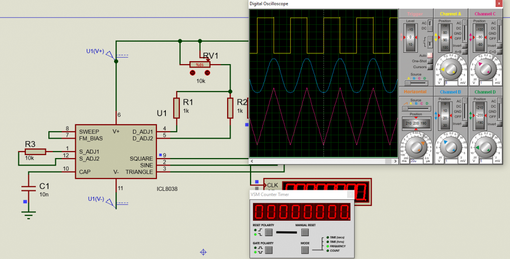
Fixed frequency diagram:

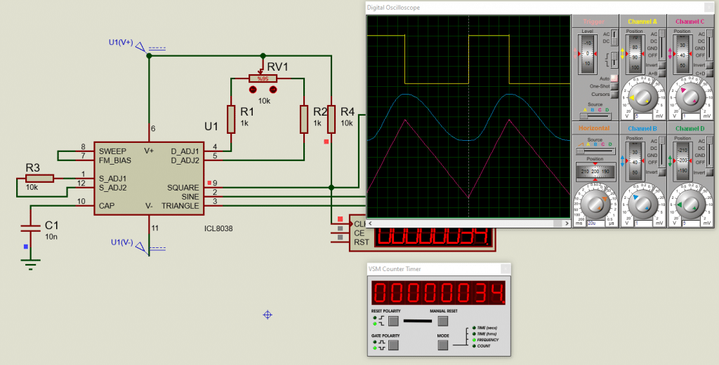
Here you need to use a dual power supply. I used +12V & -12V in simulation. It worked fine. You can download the proteus file from here.
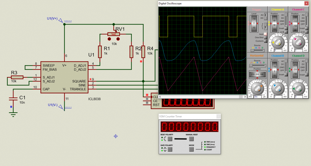
Variable frequency diagram:
For variable frequency, you need to change the diagram a little bit like this one:
And if you want to keep both, you can do that too by using multiple variable resistors.
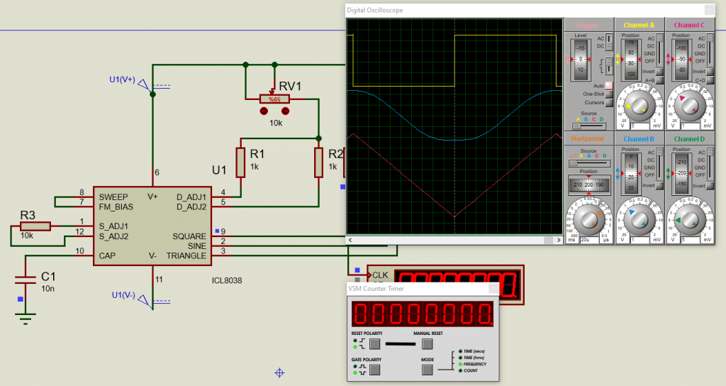
Result:
While simulating, I got a good result from this IC. I can change the swift tuning RV1. For frequency tune, you need to do a little modification of this circuit diagram.

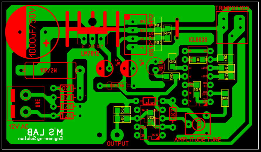
PCB:
I’ve made the PCB for this too. You can check this if you wish you can make one too. As I use Sprint Layout 6.0 for most of the project, so I’ll share the design file with you.
Hope you enjoyed the project and it helped you make your own function generator/waveform generator whatever you call it. If you need any help feel free to contact me. Thank you.
Liked this article? Subscribe to our newsletter:
or,
Visit LabProjectsBD.com for more inspiring projects and tutorials.
Thank you!
Check this out: 5 coolest multimeters you can buTop 5 Digital Multimeters for beginners


0 Comments