In this article, we are going to make a complete project with RFID. Many students made this project and submitted it to their institute as their final year project. You can make this project for your final year project too. So let’s start our RFID Based Toll Collection System.
⚠️Disclaimer:
Working with electricity involves serious risk. Ensure you have the necessary skills and take proper safety precautions before attempting any electrical projects. Proceed at your own risk — the author assumes no responsibility for any damage, injury, or issues resulting from the use or misuse of the information provided.
All content on this website is original and protected by copyright. Please do not copy or reproduce content without permission. While most of the resources shared here are open-source and freely accessible for your learning and benefit, your respect for our intellectual effort is appreciated.
If you find our tutorials helpful, consider supporting us by purchasing related materials or sharing our work — it helps keep the content flowing.
Need help or have questions? Leave a comment below — the author is always happy to assist!
Table of Contents
About this project:
In this project, we are going to take a toll collection system. A toll collection system can be found near any bridge or similar locations in the street where each vehicle has to pay to cross that part of the road. In most countries, this toll is manually collected and a printed slip is provided by a tollman.
Here in this project, we are going to make something automated for this purpose. As an educational project, we are going to make a basic system where each vehicle will have a preregistered unique ID (using an RFID card). When the driver arrives at the toll plaza, the driver punches the ID to a specific device where the RFID reader is placed.
Then the system detects the vehicle ID and cuts the fee from that card. If the card balance is low, the driver has to recharge the card.
In this project, we are using a microcontroller (PIC16F877A), an RFID module (RDM6300), a servo motor (SG90), a 16×2 LCD, an IR sensor, and some associated components.
Block diagram:
The block diagram of our project is:

About Block Diagram:
In the block diagram, we can see that our project has 3 inputs and 3 outputs. The IR sensors detect vehicle arrival and RFID scans the ID. Then the micro-controller drives the servo motor to pass the vehicle. The LCD display is used to show information and buzzer for alarming purposes. The button is used to recharge the card. And the power supply which is supplying 5V DC to MCU from the AC220V line.
Circuit diagram:
Now, we will see the circuit diagram of our RFID Based Toll Collection System:

Working principle:
Here in our project, an IR transmitter led and IR receiver diode is used to detect the vehicle arrival. D1 is an IR transmitter which is transmitting an Infra-Red beam to the receiver diode. The receiver diode is inversely connected with a pull-up resistor R5 which is driving a transistor Q2. When there is an IR beam detected by the receiver diode, the diode acts as a conductive path. The transistor Q2 then acts as cut-off mode. So we are getting 5V due to the pulled up resistor R6 which is feed to the RA0 pin of the PIC16F877A microcontroller.
When there is a vehicle in between this transmitter and receiver, no IR beam is detected thus 0V is found at RA0 pin due to Transistor Q2’s on mode. In this way, we can detect any vehicle that has arrived before the toll plaza if we make a sensing gate just before the toll plaza.

Now, the RFID module U2 (RDM6300) is connected via UART. The micro-controller has Tx & Rx pin for the UART module and the RDM6300 also has Tx and Rx pin. The Tx pin of RDM6300 is connected with the Rx pin of MCU. When the RFID module detects a card ID, it prints that ID at its Tx pin, and the micro-controller reads that ID through its UART module.

16X2 LCD needs 6 pins to connect with micro-controller which is done from RA0 to RA5 pin of PIC16F877A. Information is printed from time to time on this LCD screen.

The servo motor (SG90) which is working as our gate operator is connected to the RD7 pin of the micro-controller. A pulse is generated at this pin to drive the servo motor.

The buzzer BUZ1 is rated 12V. That is why we need a transistor Q1 to drive the buzzer. Both of our transistors is BC547 general purpose transistor.
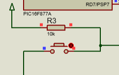
The recharge button which is pulled up by a resistor R3 is connected to the RD3 pin of the MCU. This pin is set as input and active low mode triggers the button more.
Finally, the power supply unit of our project is designed with a step-down transformer which is converting the AC220V line into 12V ac. Then a bridge diode and a filter capacitor C1 make it unregulated DC12V. This 12V is supplied to a linear voltage regulator LM7805. This voltage regulator supplies 5V regulated voltage to micro-controller and LCD and servo motor. A filter capacitor C2 is required just after the voltage regulator output to make it more smooth.
Flow chart:
Here is the flow chart of this project:

Coding:
I used mikroC pro for PIC v7.6 to do the programming. Here is the code for our project:
/*******************************************************************************
* Program for, RFID Parking System for Ctg. *
* Written by_ Engr. Mithun K. Das *
* MCU: PIC16F877A; X-Tal:8MHz *
* Date:24-05-2016 *
*******************************************************************************/
// LCD module connections
sbit LCD_RS at RB5_bit;
sbit LCD_EN at RB4_bit;
sbit LCD_D4 at RB3_bit;
sbit LCD_D5 at RB2_bit;
sbit LCD_D6 at RB1_bit;
sbit LCD_D7 at RB0_bit;
sbit LCD_RS_Direction at TRISB5_bit;
sbit LCD_EN_Direction at TRISB4_bit;
sbit LCD_D4_Direction at TRISB3_bit;
sbit LCD_D5_Direction at TRISB2_bit;
sbit LCD_D6_Direction at TRISB1_bit;
sbit LCD_D7_Direction at TRISB0_bit;
// End LCD module connections
void Lcd_COut(char row, char col, const char *cptr)
{
char chr = 0; //first, it is used as empty string
Lcd_Out(row, col, &chr); //nothing to write but set position.
for ( ; chr = *cptr ; ++cptr ) Lcd_Chr_CP(chr); //out in loop
}
char rfid[13];
char i;
short vehicle = 0,vehicle_mask = 1;
unsigned int balance1 = 100,balance2 = 100,balance3 = 100,balance4 = 100,balance5 = 100;
void Disp_Balance(short row, short coloum,unsigned int bal)
{
char msg_bl[] = "000TK";
msg_bl[0] = bal/100 + 48;
msg_bl[1] = (bal/10)%10 + 48;
msg_bl[2] = bal%10 + 48;
Lcd_Out(row,coloum,msg_bl);
Delay_ms(100);
}
#define Buzzer RD6_bit
#define Recharge RD3_bit
#define LED RD2_bit
#define ON 1
#define OFF 0
void beep()
{
Buzzer = ON;LED = ON;Delay_ms(50);Buzzer = OFF;LED = OFF;Delay_ms(50);//set a pulse
}
void InitTimer1()
{
T1CON = 0x31;
TMR1IF_bit = 0;
TMR1H = 0x0B;
TMR1L = 0xDB;
TMR1IE_bit = 1;
INTCON = 0xC0;
}
unsigned int clk=0,servo_clk=0,ddd=0;
void Interrupt() iv 0x0004 ics ICS_AUTO
{
if (TMR1IF_bit)
{
TMR1IF_bit = 0;
TMR1H = 0x0B;
TMR1L = 0xDB;
clk = servo_clk;
RD7_bit = 0;
for(ddd=0;ddd<clk;ddd++)
{
Delay_us(1);
RD7_bit = 1;
}
RD7_bit = 0;
}
}
void Delay2Sec()
{
unsigned int d;
for(d=0;d<2000;d++)
{
Delay_ms(1);
}
}
bit a,b,c,d;
int number=0;
char space[]="00";
void main()
{
TRISA = 0xFF;//all input
TRISD3_bit = 1;//set as input
TRISD7_bit = 0;
TRISD6_bit = 0;
ADCON1 = 0x07;//all digital selection
ADCON0 = 0x00;//ADC Off
InitTimer1();
servo_clk = 240;
beep();
Lcd_Init(); // Initialize LCD
Lcd_Cmd(_LCD_CLEAR); // Clear display
Lcd_Cmd(_LCD_CURSOR_OFF); // Cursor off
Lcd_COut(1,1,"RFID Parking"); // Write text in first row
Lcd_COut(2,1,"System");
Delay2Sec();
UART1_Init(9600); // Initialize UART, 9600 baud rate
Delay2Sec();
//rfid[12] = '\0'; // String Terminating Character
Lcd_Cmd(_LCD_CLEAR); // Clear display
beep();beep();
a=0;b=0;c=0;
while(1)
{
out:
if(vehicle)
{
vehicle = 0;
beep();beep();
Lcd_Cmd(_LCD_CLEAR);
Lcd_COut(1,1,"Vehicle Arrived ");
Delay2Sec();
servo_clk = 240; //240 = close; 115 = open
Lcd_Cmd(_LCD_CLEAR);
top:
Lcd_COut(1,1,"Reading RFID ");
vehicle_mask = 1;
if(vehicle_mask)
{
top1:
if(UART1_Data_Ready()) // If UART Data Ready
{
for(i=0;i<12;) // To Read 12 characters of the card
{
if(UART1_Data_Ready())
{
rfid[i] = UART1_Read();
i++;
}
}
// Check For Errors
if((rfid[0] ^ rfid[2] ^ rfid[4] ^ rfid[6] ^ rfid[8] == rfid[10]) && (rfid[1] ^ rfid[3] ^ rfid[5] ^ rfid[7] ^ rfid[9] == rfid[11]))
{
beep();beep();
if(rfid[8]=='3' && rfid[9]=='6' && rfid[10]=='1' && rfid[11]=='A')//match 1
{
beep();//set a pulse
Lcd_COut(1,1,"CAT#1; T:15/- ");
if(balance1>15)
{
if(a==0)balance1-=15;
Lcd_COut(2,1,"Bal. Avail:");
Disp_Balance(2,12,balance1);
Delay2Sec();
Lcd_Cmd(_LCD_CLEAR);
Lcd_COut(1,1,"Opening Gate");
Delay2Sec();
servo_clk = 115; //240 = close; 115 = open
Delay2Sec();Delay2Sec();
Lcd_Cmd(_LCD_CLEAR);
Lcd_COut(1,1,"Closing Gate");
Delay2Sec();
servo_clk = 240; //240 = close; 115 = open
beep();beep();
a=~a;
}
else
{
Lcd_COut(2,1,"Low Balance");
Delay2Sec();
}
}
else if(rfid[8]=='3' && rfid[9]=='8' && rfid[10]=='0' && rfid[11]=='F')//match 2
{
beep();//set a pulse
Lcd_COut(1,1,"CAT#2; T:25/- ");
if(balance2>25)
{
if(b==0)balance2-=25;
Lcd_COut(2,1,"Bal. Avail:");
Disp_Balance(2,12,balance2);
Delay2Sec();
Lcd_Cmd(_LCD_CLEAR);
Lcd_COut(1,1,"Opening Gate");
Delay2Sec();
servo_clk = 115; //240 = close; 115 = open
Delay2Sec();Delay2Sec();
Lcd_Cmd(_LCD_CLEAR);
Lcd_COut(1,1,"Closing Gate");
Delay2Sec();
servo_clk = 240; //240 = close; 115 = open
beep();beep();
b=~b;
}
else
{
Lcd_COut(2,1,"Low Balance");
Delay2Sec();
}
}
else if(rfid[8]=='C' && rfid[9]=='D' && rfid[10]=='3' && rfid[11]=='2')//match 2
{
beep();//set a pulse
Lcd_COut(1,1,"CAT#3; T:35/- ");
if(balance3>35)
{
if(c==0)balance3-=35;
Lcd_COut(2,1,"Bal. Avail:");
Disp_Balance(2,12,balance3);
Delay2Sec();
Lcd_Cmd(_LCD_CLEAR);
Lcd_COut(1,1,"Opening Gate");
Delay2Sec();
servo_clk = 115; //240 = close; 115 = open
Delay2Sec();Delay2Sec();
Lcd_Cmd(_LCD_CLEAR);
Lcd_COut(1,1,"Closing Gate");
Delay2Sec();
servo_clk = 240; //240 = close; 115 = open
beep();beep();
c=~c;
}
else
{
Lcd_COut(2,1,"Low Balance");
Delay2Sec();
}
}
else
{
beep();beep();beep();//set a pulse
Lcd_COut(1,1,"UNREGISTERED ID ");
Delay2Sec();
servo_clk = 240; //240 = close; 115 = open
goto top;
}
vehicle_mask = 0;
vehicle = 0;
goto out;
}
else
{
Lcd_COut(2,1,"Error ");
Buzzer = ON;Delay_ms(80);Buzzer = OFF;//set a pulse
goto top;
}
}
else
{
goto top1;
}
}
}
else
{
Lcd_COut(1,1,"Waiting for ");
Lcd_COut(2,1,"Vehicle arrival ");
number = 10-(a+b+c);
space[0] = number/10 + 48;
space[1] = number%10 + 48;
Lcd_Out(1,15,space);
if(RA0_bit==0)vehicle = 1;
servo_clk = 240; //240 = close; 115 = open
if(!Recharge)
{
beep();
Lcd_Cmd(_LCD_CLEAR); // Clear display
Lcd_COut(1,1,"Recharge_");
Delay2Sec();
Lcd_Cmd(_LCD_CLEAR); // Clear display
Lcd_COut(1,1,"Reading RFID ");
Delay2Sec();
beep();
recharge:
if(UART1_Data_Ready()) // If UART Data Ready
{
for(i=0;i<12;) // To Read 12 characters of the card
{
if(UART1_Data_Ready())
{
rfid[i] = UART1_Read();
i++;
}
}
// Check For Errors
if((rfid[0] ^ rfid[2] ^ rfid[4] ^ rfid[6] ^ rfid[8] == rfid[10]) && (rfid[1] ^ rfid[3] ^ rfid[5] ^ rfid[7] ^ rfid[9] == rfid[11]))
{
beep();beep();
Lcd_Cmd(_LCD_CLEAR); // Clear display
Lcd_COut(1,1,"RFID:");
Lcd_Out(2,1,rfid);
//do balance cutting
Delay2Sec();
Lcd_Cmd(_LCD_CLEAR); // Clear display
if(rfid[8]=='3' && rfid[9]=='6' && rfid[10]=='1' && rfid[11]=='A')//match 1
{
beep();//set a pulse
Lcd_COut(1,1,"Cat # 1");
Lcd_COut(2,1,"Recharge: 100/-");
Delay2Sec();
balance1+=100;
Lcd_Cmd(_LCD_CLEAR);
Lcd_COut(1,1,"Cat # 1");
Lcd_COut(2,1,"Bal. Avail:");
Disp_Balance(2,12,balance1);
Delay2Sec();
Lcd_Cmd(_LCD_CLEAR);
beep();beep();
}
else if(rfid[8]=='3' && rfid[9]=='8' && rfid[10]=='0' && rfid[11]=='F')//match 2
{
beep();//set a pulse
Lcd_COut(1,1,"Cat # 2");
Lcd_COut(2,1,"Recharge: 100/-");
Delay2Sec();
balance2+=100;
Lcd_Cmd(_LCD_CLEAR);
Lcd_COut(1,1,"Cat # 2");
Lcd_COut(2,1,"Bal. Avail:");
Disp_Balance(2,12,balance2);
Delay2Sec();
Lcd_Cmd(_LCD_CLEAR);
beep();beep();
}
else if(rfid[8]=='C' && rfid[9]=='D' && rfid[10]=='3' && rfid[11]=='2')//match 2
{
beep();//set a pulse
Lcd_COut(1,1,"Cat # 3");
Lcd_COut(2,1,"Recharge: 100/-");
Delay2Sec();
balance3+=100;
Lcd_Cmd(_LCD_CLEAR);
Lcd_COut(1,1,"Cat # 3");
Lcd_COut(2,1,"Bal. Avail:");
Disp_Balance(2,12,balance3);
Delay2Sec();
Lcd_Cmd(_LCD_CLEAR);
beep();beep();
}
else
{
beep();beep();beep();//set a pulse
Lcd_COut(1,1,"UNREGISTERED ID ");
Delay2Sec();
servo_clk = 240; //240 = close; 115 = open
Lcd_Cmd(_LCD_CLEAR); // Clear display
Lcd_COut(1,1,"Try again_");
Delay2Sec();
Lcd_Cmd(_LCD_CLEAR); // Clear display
Lcd_COut(1,1,"Reading RFID ");
Delay2Sec();
beep();
goto recharge;
}
goto out;
}
else
{
Lcd_COut(2,1,"Error ");
Buzzer = ON;Delay_ms(80);Buzzer = OFF;//set a pulse
goto recharge;
}
}
else
{
goto recharge;
}
}
}
}//while(1)
}//void main
//
Download the mikroC file of this project.
Code explanation:
Among other general functions, here is an important function to control the servo motor.
void InitTimer1()
{
    T1CON         = 0x31;
    TMR1IF_bit    = 0;
    TMR1H         = 0x0B;
    TMR1L         = 0xDB;
    TMR1IE_bit    = 1;
    INTCON        = 0xC0;
}

unsigned int clk=0,servo_clk=0,ddd=0;
void Interrupt() iv 0x0004 ics ICS_AUTO
{
    if (TMR1IF_bit)
    {
         TMR1IF_bit = 0;
         TMR1H         = 0x0B;
         TMR1L         = 0xDB;
         clk = servo_clk;
         RD7_bit = 0;
         for(ddd=0;ddd<clk;ddd++)
         {
             Delay_us(1);
             RD7_bit = 1;
         }
         RD7_bit = 0;
    }
}
This timer interrupt function is generating a periodic pulse of 2-20ms to drive the servo motor. As we know that the servo motor is driven by a pulse of 2-20ms duration to set the direction. We can set that pulse duration with the variable ‘servo_clk’ here.
if(UART1_Data_Ready()) // If UART Data Ready
                 {
                     for(i=0;i<12;) // To Read 12 characters  of the card
                     {
                         if(UART1_Data_Ready())
                         {
                             rfid[i] = UART1_Read();
                             i++;
                         }
                     }
                     // Check For Errors
                     if((rfid[0] ^ rfid[2] ^ rfid[4] ^ rfid[6] ^ rfid[8] == rfid[10]) && (rfid[1] ^ rfid[3] ^ rfid[5] ^ rfid[7] ^ rfid[9] == rfid[11]))
                     {
// ..other codes.. //
                        }
//..other codes..//
}
In this block, the RFID tag is being read by the UART module of the micro-controller. After reading ID, checked the id for error. If there is no error, the next step can be done.
if(rfid[8]=='3' && rfid[9]=='6' && rfid[10]=='1' && rfid[11]=='A')//match 1
{
   beep();//set a pulse
   Lcd_COut(1,1,"CAT#1; T:15/-   ");
   if(balance1>15)
   {
      if(a==0)balance1-=15;
      Lcd_COut(2,1,"Bal. Avail:");
      Disp_Balance(2,12,balance1);
      Delay2Sec();
      Lcd_Cmd(_LCD_CLEAR);
      Lcd_COut(1,1,"Opening Gate");
      Delay2Sec();
      servo_clk = 115; //240 = close; 115 = open
      Delay2Sec();Delay2Sec();
      Lcd_Cmd(_LCD_CLEAR);
      Lcd_COut(1,1,"Closing Gate");
      Delay2Sec();
      servo_clk = 240; //240 = close; 115 = open
      beep();beep();
      a=~a;
   }
   else
   {
      Lcd_COut(2,1,"Low Balance");
      Delay2Sec();
   }
}
In this part, ID is compared with an ID. As we are not using any external memory card or database, so we are comparing direct ID to find the vehicle ID.
After finding ID, an amount is charged according to the vehicle class. For example, 15/- is cut from this id.
Recharging is almost in similar ways, I hope you’ll understand that easily.
You can read this article too: How to make a Single Phase AC voltmeter using PIC16F76 & Capacitor power supply
Result:
Here is the simulation result of our project:


PCB diagram:
Here is the PCB diagram of this project what I used for this project. You can make one for yourself too.

We made this project in real life and the tested result is:


Conclusion:
In this article, we have learned how to make an RFID-based toll collecting system. I hope you have learned it well and can make one for yourself. If you need any help, feel free to contact me. Thank you.
Liked this article? Subscribe to our newsletter:
or,
Visit LabProjectsBD.com for more inspiring projects and tutorials.
Thank you!


0 Comments