For an incubator, a temperature controller is the main control unit. There are many temperature controllers in the market. But here is a simple one, I think the most simple one that you can make yourself. The circuit required no external power supply as it uses a simple capacitor power supply to run directly from AC. So let’s start our Simple Analog temperature Controller.
⚠️Disclaimer:
Working with electricity involves serious risk. Ensure you have the necessary skills and take proper safety precautions before attempting any electrical projects. Proceed at your own risk — the author assumes no responsibility for any damage, injury, or issues resulting from the use or misuse of the information provided.
All content on this website is original and protected by copyright. Please do not copy or reproduce content without permission. While most of the resources shared here are open-source and freely accessible for your learning and benefit, your respect for our intellectual effort is appreciated.
If you find our tutorials helpful, consider supporting us by purchasing related materials or sharing our work — it helps keep the content flowing.
Need help or have questions? Leave a comment below — the author is always happy to assist!
Warning!: The circuit uses direct AC. Connect the phase and neutral as like the circuit. Also, the circuit may carry live voltage. Do work on your own responsibility. Always check the phase using a tester before touching any part directly.
Table of Contents
The basic principle of a temperature controller?
A temperature controller can be of different types based on its control mechanism. But the basic is very simple. Sense the temperature, compare it with a reference value. Then turn the heater or cooler on/off based on that reference value. A simple comparator can work for this purpose.
Now, what are some advanced features a temperature controller may have?
- PID control
- Hysteresis control
- Fuzzy Logic control
Most of the available incubator controllers use either Fuzzy or PID to maintain the temperature and keeping a good correction speed. And simple ones use hysteresis control.
Here are some popular ones from different sources.
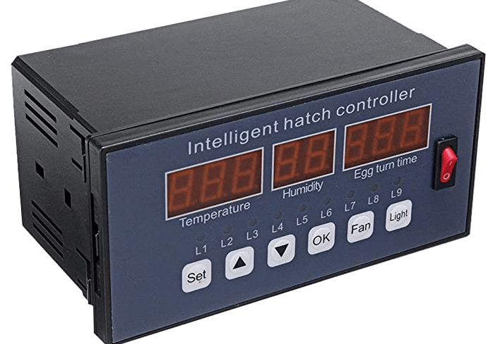
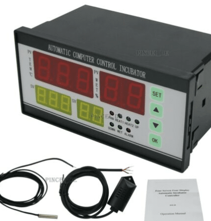

These are multi-functional. Also a little complex to make and easy to use. But here we are going to make one for ourselves. Let’s see what we can make.
You may find this helpful: Transformerless power supply design guide in detail with calculator
Circuit diagram:
Circuit diagram for our Simple Analog temperature Controller:

Here, the red wire is the phase and the black wire is neutral. The top block of the circuit is a capacitor power supply. There is an article on this in my blog. You can read that too. This one is one of that kind with little modification as we need a common ground.
The C1 is the main capacitor here for this power supply. It should be good quality, better using X2 type but you can use as I used in my circuit. I got these capacitors from a Japanese company and bought thousands for my different products. Capacitor feedback is very good and satisfactory.
For BR1, you can use 1N4007 X 4. And rest of the components need no explanation. Just use a good Zener diode of 1W or larger. The power supply circuit supplies sufficient current for our circuit. The R1 (47R/2W) becomes hot so it’s better to place it keeping it a little high from the PCB surface.
The temperature control circuit is using a common Op-Amp LM358 in comparator mode. Resistor R6 (220K) is used for hysteresis. This is important. Otherwise, the relay will be turned on & off at the same point which will kill the relay as well as the loads. So a hysteresis is important. The thermistor used here is an NTC-based 10K thermistor. The rest of the part of the circuit needs no explanation I think.
Here keep in mind that, as this is a very simple circuit, there are no extra features added. A single circuit can be used for both the heater and the cooler. But for better heat regulation, I suggest using two circuits. One for heating purposes, the other for cooling purposes. By setting the temperature range little wide tuning the POT RV1, good heat regulation is possible.
PCB:
I made this circuit in PCB. Here is the design:


And the transformer version:

Test Result:
Circuit with 2 Relays:

You can use two relays and set them for the cooler and heater individually. Keep a good hysteresis gap between the heater and cooler. For example, for incubator use, you can set the cooler on at 38.2’C and off at 37.5’C then set the heater at 36.5’C and off at 37’C. So a gap is kept between the two switches. Which will actually help in heat management.
Note: It totally depends on experience and expertise. But why you don’t try a bit?
Conclusion:
The temperature controller circuit was very simple and I’ve demonstrated who it works. You can use this circuit on your own now. But don’t forget to give credit. I hope this article will help you. Thanks
For more interesting projects like this please don’t forget to subscribe.
Liked this article? Subscribe to our newsletter:
or,
Visit LabProjectsBD.com for more inspiring projects and tutorials.
Thank you!
Check this: 6V Lead-Acid battery charger circuit


3 Comments
Joy · 19/06/2021 at 11:04 am
Good Job.
MKDas · 19/06/2021 at 11:10 am
Thanks
eng Kevin · 12/08/2022 at 9:25 pm
Good job, I will give it a try