In this article, we are going to make a Digital Clock using a PIC microcontroller & RTC DS1307. Here we can use a suitable PIC microcontroller that is available in the market or in our lab. I think PIC16F73 will be the best one. With this microcontroller, we’ll interface RTC DS1307 through the I2C protocol. So let’s start the project.
⚠️Disclaimer:
Working with electricity involves serious risk. Ensure you have the necessary skills and take proper safety precautions before attempting any electrical projects. Proceed at your own risk — the author assumes no responsibility for any damage, injury, or issues resulting from the use or misuse of the information provided.
All content on this website is original and protected by copyright. Please do not copy or reproduce content without permission. While most of the resources shared here are open-source and freely accessible for your learning and benefit, your respect for our intellectual effort is appreciated.
If you find our tutorials helpful, consider supporting us by purchasing related materials or sharing our work — it helps keep the content flowing.
Need help or have questions? Leave a comment below — the author is always happy to assist!
Table of Contents
What is RTC?
A RTC is an integrated circuit that contains a timer that supplies the time of day (and often, the date). An RTC generally contains a long-life battery to allow it to keep track of the time even when there is no power applied. Dallas is the most popular RTC production company out there. One of its products is DS1307. For our project, Digital Clock using a PIC microcontroller & RTC DS1307, this IC is like the heart.
You can read this article here to learn more about RTC.


DS1307 is a very common RTC in the market. 56-bytes of data is stored in its NV SRAM. Real-Time Clock (RTC) Counts Seconds, Minutes, Hours, Date of the Month, Month, Day of the week, and Year with Leap-Year Compensation Valid Up to 2100.
To more about DS1307 please the datasheet from here.
To interface DS1307, we need two pull-up resistors with its SCL and SDA pins which are used for I2C data communication. Besides, a crystal of 32.768KHz is used for its oscillation. A backup battery of 3V is required to store the data and the time counting when the power is out.
A 47mAh Li-ion CR2032 battery can give a backup of 10years.
Circuit diagram:

This is the simple communication circuit that will be followed. As you see, the MCU and RTC are connected through SCL and SDA pins. But the problem with PIC16F73 is this there is no master I2C module inside of this microcontroller. It has only a slave I2C module built-in. That is why, when we need to use the I2C, we have to use the software I2C library from mikroC.
By keeping a display, we can redraw the circuit of our project “Digital Clock using a PIC microcontroller & RTC DS1307”:
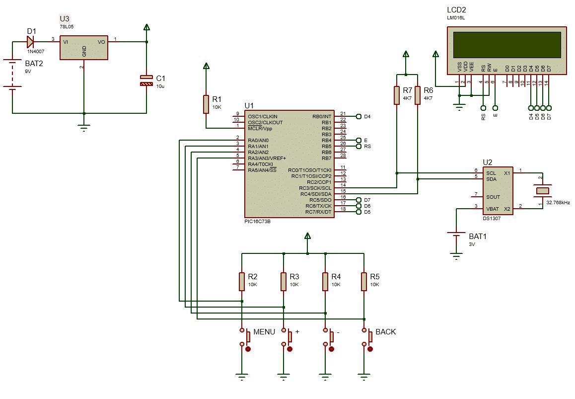
Circuit explanation:
The circuit is very simple. 16X2 LCD display is used as our display. 4 buttons are used for time setting which is pulled up by 10K resistors. Then RTC and power supply circuit. You need to use a crystal oscillator of 20MHz for MCU in the project which is not showing in the circuit diagram.
You may find this article useful too: How to remove noise/garbage from the HD44780 LCD display
MikroC coding:
Here is the coding of our project, Digital Clock using a PIC microcontroller & RTC DS1307:
/*******************************************************************************
Program for RTC with ds1307
Program Written by_ Engr. Mithun K. Das; [email protected]
MCU:PIC16F73; X-Tal: 20MHz, Compiler: mikroC pro for PIC v7.6.0
Date: 05-07-2021;
*******************************************************************************/
// LCD module connections
sbit LCD_RS at RB5_bit;
sbit LCD_EN at RB4_bit;
sbit LCD_D4 at RB0_bit;
sbit LCD_D5 at RC7_bit;
sbit LCD_D6 at RC6_bit;
sbit LCD_D7 at RC5_bit;

sbit LCD_RS_Direction at TRISB5_bit;
sbit LCD_EN_Direction at TRISB4_bit;
sbit LCD_D4_Direction at TRISB0_bit;
sbit LCD_D5_Direction at TRISC7_bit;
sbit LCD_D6_Direction at TRISC6_bit;
sbit LCD_D7_Direction at TRISC5_bit;
// End LCD module connections


// Software I2C connections
sbit Soft_I2C_Scl           at RC3_bit;
sbit Soft_I2C_Sda           at RC4_bit;
sbit Soft_I2C_Scl_Direction at TRISC3_bit;
sbit Soft_I2C_Sda_Direction at TRISC4_bit;
// End Software I2C connections


#define    menu_button    RA0_bit
#define    plus_button    RA1_bit
#define    minus_button   RA2_bit
#define    back_button    RA3_bit


int second,minute,hour;
int hr,day,dday,month,year,ap,app;
unsigned short set_timer=0;
unsigned short mode=0;//run mode

unsigned short set_count = 0;
bit old_state1;

char time[] = "00:00:00    ";
char date[] = "00-00-00    ";

unsigned short read_ds1307(unsigned short address)
{
  unsigned short r_data;
  Soft_I2C_Start();
  Soft_I2C_Write(0xD0); //address 0x68 followed by direction bit (0 for write, 1 for read) 0x68 followed by 0 --> 0xD0
  Soft_I2C_Write(address);
  Soft_I2C_Start();
  Soft_I2C_Write(0xD1); //0x68 followed by 1 --> 0xD1
  r_data=Soft_I2C_Read(0);
  Soft_I2C_Stop();
  return(r_data);
}

void write_ds1307(unsigned short address,unsigned short w_data)
{
  Soft_I2C_Start(); // issue I2C start signal
  //address 0x68 followed by direction bit (0 for write, 1 for read) 0x68 followed by 0 --> 0xD0
  Soft_I2C_Write(0xD0); // send byte via I2C (device address + W)
  Soft_I2C_Write(address); // send byte (address of DS1307 location)
  Soft_I2C_Write(w_data); // send data (data to be written)
  Soft_I2C_Stop(); // issue I2C stop signal
}


unsigned char BCD2UpperCh(unsigned char bcd)
{
  return ((bcd >> 4) + '0');
}


unsigned char BCD2LowerCh(unsigned char bcd)
{
  return ((bcd & 0x0F) + '0');
}


int Binary2BCD(int a)
{
   int t1, t2;
   t1 = a%10;
   t1 = t1 & 0x0F;
   a = a/10;
   t2 = a%10;
   t2 = 0x0F & t2;
   t2 = t2 << 4;
   t2 = 0xF0 & t2;
   t1 = t1 | t2;
   return t1;
}


int BCD2Binary(int a)
{
   int r,t;
   t = a & 0x0F;
   r = t;
   a = 0xF0 & a;
   t = a >> 4;
   t = 0x0F & t;
   r = t*10 + r;
   return r;
}

void get_time()
{
    second = read_ds1307(0);
    minute = read_ds1307(1);
    hour = read_ds1307(2);
    dday = read_ds1307(3);
    day = read_ds1307(4);
    month = read_ds1307(5);
    year = read_ds1307(6);

    time[0] = BCD2UpperCh(hour);
    time[1] = BCD2LowerCh(hour);
    time[3] = BCD2UpperCh(minute);
    time[4] = BCD2LowerCh(minute);
    time[6] = BCD2UpperCh(second);
    time[7] = BCD2LowerCh(second);

    date[0] = BCD2UpperCh(day);
    date[1] = BCD2LowerCh(day);
    date[3] = BCD2UpperCh(month);
    date[4] = BCD2LowerCh(month);
    date[6] = BCD2UpperCh(year);
    date[7] = BCD2LowerCh(year);
}


void main()
{
  TRISA = 0x0F;//RA0 input
  TRISB = 0x00;//all output
  TRISC = 0xFF;//all input
  ADCON1= 0x07;//all digital
  ADCON0= 0x00;//ADC OFF

  Soft_I2C_Init();           // Initialize Soft I2C communication
  Lcd_Init();                // Initialize LCD
  Lcd_Cmd(_LCD_CLEAR);       // Clear LCD display
  Lcd_Cmd(_LCD_CURSOR_OFF);  // Turn cursor off

  while(1)
  {

      if(!menu_button && old_state1)
      {
         old_state1=0;//reset mask
         if(set_count<6)set_count++;
         else set_count = 1;
         Lcd_Cmd(_LCD_CLEAR);
         mode = 1;//edit mode
      }
      if(menu_button && !old_state1) old_state1 = 1;//set mask again for next press

      if(!back_button)
      {
         mode = 0;//run mode
         set_count = 0;
      }


      if(mode)//edit mode
      {
          Lcd_Out(1,1,"EDIT");
          Lcd_Out(2,1,"CLOCK"); //edit clock
          get_time();
          Lcd_Out(1,7, time);
          Lcd_Out(2,7, date);
          Delay_ms(100);
      }
      else
      {
          get_time();
          Lcd_Out(1,1," Time:");
          Lcd_Out(2,1," Date:");
          Lcd_Out(1,7, time);
          Lcd_Out(2,7, date);
          Delay_ms(100);
      }

      if(set_count) //if set_cnt>0
      {
          switch(set_count)
          {
            case 1:
                     hour = BCD2Binary(hour);
                     if(!plus_button)hour = hour + 1;
                     if(!minus_button)hour = hour - 1;
                     if(hour>= 24)
                        hour = 0;
                        hour = Binary2BCD(hour);
                     write_ds1307(2, hour); //write hour
                     Lcd_Out(1,7,"  ");
                     Delay_ms(100);
                     break;
            case 2:
                     minute = BCD2Binary(minute);
                     if(!plus_button)minute+=1;
                     if(!minus_button)minute -= 1;
                     if(minute >= 60)
                        minute = 0;
                     if(minute < 0)
                        minute = 59;
                        minute = Binary2BCD(minute);
                     write_ds1307(1, minute); //write min
                     Lcd_Out(1,10,"  ");
                     Delay_ms(100);
                     break;
            case 3:
                      write_ds1307(0,0x00); //Reset second to 0 sec. and start Oscillator
                      Delay_ms(100);
                    break;
            case 4:
                     day = BCD2Binary(day);
                     if(!plus_button)day +=1;
                     if(!minus_button)day -=1;
                     day = Binary2BCD(day);
                     if(day >= 0x32)
                        day = 1;
                     if(day <= 0)
                        day = 0x31;
                        write_ds1307(4, day);
                     Lcd_Out(2,7,"  ");
                     Delay_ms(100);
                     break;
            case 5:
                    month = BCD2Binary(month);
                    if(!plus_button)month +=1;
                    if(!minus_button)month -=1;
                    month = Binary2BCD(month);
                    if(month > 0x12)
                      month = 1;
                    if(month <= 0)
                      month = 0x12;
                      write_ds1307(5,month);
                    Lcd_Out(2,10,"  ");
                    Delay_ms(100);
                    break;
            case 6:
                    year = BCD2Binary(year);
                    if(!plus_button)year +=1;
                    if(!minus_button)year -=1;
                    year = Binary2BCD(year);
                    if(year <= -1)
                       year = 0x99;
                    if(year >= 0x50)
                       year = 0;
                       write_ds1307(6, year);
                    Lcd_Out(2,13,"  ");
                    Delay_ms(100);
                    break;
          }
      }

  }//end of while(1)

}//end of void
Check the other article where the code is done for 12hr mode: Digital Clock with DS3231 & PIC microcontroller
Code explanation:
After the LCD pin configuration, this code block activates the pins for software I2C communication:
// Software I2C connections
sbit Soft_I2C_Scl           at RC3_bit;
sbit Soft_I2C_Sda           at RC4_bit;
sbit Soft_I2C_Scl_Direction at TRISC3_bit;
sbit Soft_I2C_Sda_Direction at TRISC4_bit;
// End Software I2C connections
unsigned short read_ds1307(unsigned short address)
{
  unsigned short r_data;
  Soft_I2C_Start();
  Soft_I2C_Write(0xD0); //address 0x68 followed by direction bit (0 for write, 1 for read) 0x68 followed by 0 --> 0xD0
  Soft_I2C_Write(address);
  Soft_I2C_Start();
  Soft_I2C_Write(0xD1); //0x68 followed by 1 --> 0xD1
  r_data=Soft_I2C_Read(0);
  Soft_I2C_Stop();
  return(r_data);
}

void write_ds1307(unsigned short address,unsigned short w_data)
{
  Soft_I2C_Start(); // issue I2C start signal
  //address 0x68 followed by direction bit (0 for write, 1 for read) 0x68 followed by 0 --> 0xD0
  Soft_I2C_Write(0xD0); // send byte via I2C (device address + W)
  Soft_I2C_Write(address); // send byte (address of DS1307 location)
  Soft_I2C_Write(w_data); // send data (data to be written)
  Soft_I2C_Stop(); // issue I2C stop signal
}
Then in the read and write function, it is simply communicating with the RTC. To understand this function, you should read the datasheet again:


Here are two calculators that you may need to calculate the commands:
Binary to Hex Converter & Binay Calculator.
Here as you see, we are calculating in binary. But our DS1307 is BCD coded. That is why, each time we write or read, we need a BDC to Binary and Binary to BCD converter. It is a little complex to explain. You can take help from this calculator. But I’ve done it in the code. As mikroC doesn’t have this converter library, little code was required.
int Binary2BCD(int a)
{
   int t1, t2;
   t1 = a%10;
   t1 = t1 & 0x0F;
   a = a/10;
   t2 = a%10;
   t2 = 0x0F & t2;
   t2 = t2 << 4;
   t2 = 0xF0 & t2;
   t1 = t1 | t2;
   return t1;
}


int BCD2Binary(int a)
{
   int r,t;
   t = a & 0x0F;
   r = t;
   a = 0xF0 & a;
   t = a >> 4;
   t = 0x0F & t;
   r = t*10 + r;
   return r;
}
Afterward, the Get_time function is a simple one to read the time and date.
void get_time()
{
    second = read_ds1307(0);
    minute = read_ds1307(1);
    hour = read_ds1307(2);
    dday = read_ds1307(3);
    day = read_ds1307(4);
    month = read_ds1307(5);
    year = read_ds1307(6);

    time[0] = BCD2UpperCh(hour);
    time[1] = BCD2LowerCh(hour);
    time[3] = BCD2UpperCh(minute);
    time[4] = BCD2LowerCh(minute);
    time[6] = BCD2UpperCh(second);
    time[7] = BCD2LowerCh(second);

    date[0] = BCD2UpperCh(day);
    date[1] = BCD2LowerCh(day);
    date[3] = BCD2UpperCh(month);
    date[4] = BCD2LowerCh(month);
    date[6] = BCD2UpperCh(year);
    date[7] = BCD2LowerCh(year);
}
The rest of the function of our code is kept here:
void main()
{
  TRISA = 0x0F;//RA0 input
  TRISB = 0x00;//all output
  TRISC = 0xFF;//all input
  ADCON1= 0x07;//all digital
  ADCON0= 0x00;//ADC OFF

  Soft_I2C_Init();           // Initialize Soft I2C communication
  Lcd_Init();                // Initialize LCD
  Lcd_Cmd(_LCD_CLEAR);       // Clear LCD display
  Lcd_Cmd(_LCD_CURSOR_OFF);  // Turn cursor off

  while(1)
  {

      if(!menu_button && old_state1)
      {
         old_state1=0;//reset mask
         if(set_count<6)set_count++;
         else set_count = 1;
         Lcd_Cmd(_LCD_CLEAR);
         mode = 1;//edit mode
      }
      if(menu_button && !old_state1) old_state1 = 1;//set mask again for next press

      if(!back_button)
      {
         mode = 0;//run mode
         set_count = 0;
      }


      if(mode)//edit mode
      {
          Lcd_Out(1,1,"EDIT");
          Lcd_Out(2,1,"CLOCK"); //edit clock
          get_time();
          Lcd_Out(1,7, time);
          Lcd_Out(2,7, date);
          Delay_ms(100);
      }
      else
      {
          get_time();
          Lcd_Out(1,1," Time:");
          Lcd_Out(2,1," Date:");
          Lcd_Out(1,7, time);
          Lcd_Out(2,7, date);
          Delay_ms(100);
      }

      if(set_count) //if set_cnt>0
      {
          switch(set_count)
          {
            case 1:
                     hour = BCD2Binary(hour);
                     if(!plus_button)hour = hour + 1;
                     if(!minus_button)hour = hour - 1;
                     if(hour>= 24)
                        hour = 0;
                        hour = Binary2BCD(hour);
                     write_ds1307(2, hour); //write hour
                     Lcd_Out(1,7,"  ");
                     Delay_ms(100);
                     break;
            case 2:
                     minute = BCD2Binary(minute);
                     if(!plus_button)minute+=1;
                     if(!minus_button)minute -= 1;
                     if(minute >= 60)
                        minute = 0;
                     if(minute < 0)
                        minute = 59;
                        minute = Binary2BCD(minute);
                     write_ds1307(1, minute); //write min
                     Lcd_Out(1,10,"  ");
                     Delay_ms(100);
                     break;
            case 3:
                      write_ds1307(0,0x00); //Reset second to 0 sec. and start Oscillator
                      Delay_ms(100);
                    break;
            case 4:
                     day = BCD2Binary(day);
                     if(!plus_button)day +=1;
                     if(!minus_button)day -=1;
                     day = Binary2BCD(day);
                     if(day >= 0x32)
                        day = 1;
                     if(day <= 0)
                        day = 0x31;
                        write_ds1307(4, day);
                     Lcd_Out(2,7,"  ");
                     Delay_ms(100);
                     break;
            case 5:
                    month = BCD2Binary(month);
                    if(!plus_button)month +=1;
                    if(!minus_button)month -=1;
                    month = Binary2BCD(month);
                    if(month > 0x12)
                      month = 1;
                    if(month <= 0)
                      month = 0x12;
                      write_ds1307(5,month);
                    Lcd_Out(2,10,"  ");
                    Delay_ms(100);
                    break;
            case 6:
                    year = BCD2Binary(year);
                    if(!plus_button)year +=1;
                    if(!minus_button)year -=1;
                    year = Binary2BCD(year);
                    if(year <= -1)
                       year = 0x99;
                    if(year >= 0x50)
                       year = 0;
                       write_ds1307(6, year);
                    Lcd_Out(2,13,"  ");
                    Delay_ms(100);
                    break;
          }
      }

  }//end of while(1)

}//end of void
Digital Clock using a PIC microcontroller & RTC DS1307 is now ready for testing. We can simulate the circuit in proteus.
Test result:
Here is the test result of our project, Digital Clock using a PIC microcontroller & RTC DS1307:
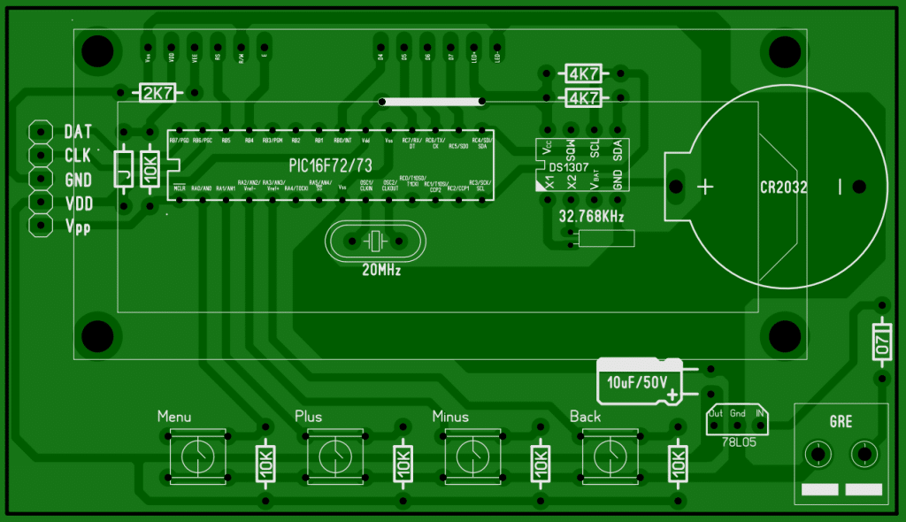
PCB diagram:
Conclusion:
This project is a good reference project for a RTC digital clock project. You can extend the features and make them more wonderful than this one. I hope this will help you with your project. Don’t forget to subscribe and share. Thanks.
Liked this article? Subscribe to our newsletter:
or,
Visit LabProjectsBD.com for more inspiring projects and tutorials.
Thank you!
This article can be helpful to you too: 6V Lead-Acid battery charger circuit


6 Comments
Joy · 10/07/2021 at 2:50 pm
Thanks.
R K Hamy · 11/07/2021 at 3:43 pm
Many Thanks!
VenuGopal k · 11/07/2021 at 10:13 pm
Hi sir iam VenuGopal from Bangalore Karnataka India sir I want LCD display timer and pcb sample ple contact me my mobile number 9916657387
I will pay the amount
MKDas · 12/07/2021 at 3:03 pm
What timer do you need? Kindly explain in detail.
hreekh · 02/08/2021 at 12:29 pm
Downloaded the full file. It works. Thank you sir. Can you please design it with SMD packages?
MKDas · 02/08/2021 at 12:31 pm
Great. Thanks. I’ll try to redesign it soon.