In this article, we are going to learn about Interfacing External EEPROM with a PIC microcontroller. All the microcontrollers do not have EEPROM but sometimes, we need to save some information in EEPROM while the MCU does not have any. In that case, external EEPROM is the only solution. So in this article, we’ll see how we can interface external EEPROM with a PIC microcontroller. So let’s start!
⚠️Disclaimer:
Working with electricity involves serious risk. Ensure you have the necessary skills and take proper safety precautions before attempting any electrical projects. Proceed at your own risk — the author assumes no responsibility for any damage, injury, or issues resulting from the use or misuse of the information provided.
All content on this website is original and protected by copyright. Please do not copy or reproduce content without permission. While most of the resources shared here are open-source and freely accessible for your learning and benefit, your respect for our intellectual effort is appreciated.
If you find our tutorials helpful, consider supporting us by purchasing related materials or sharing our work — it helps keep the content flowing.
Need help or have questions? Leave a comment below — the author is always happy to assist!
Table of Contents
About External EEPROM:
External EEPROM ICs are available in wide ranges of memory capacity and size. But one common thing is the interface mechanism. Most of the EEPROMs support the I2C protocol. Some common External EEPROMs are:
The 24 series have wide ranges of memory capacity ICs available. We can use anyone that is suitable for our work. Let’s get to the work directly.
Circuit Diagram:
For this test project, I’ll use the simple and common PIC microcontroller, PIC16F73. And another common EEPROM 24C08.
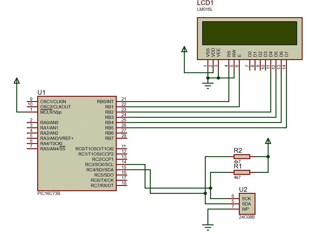
Here, R1 & R2 are important to use. The other pins of the IC are the address pins. If you want to use multiple ICs, then you need to address them separately utilizing those address pins.
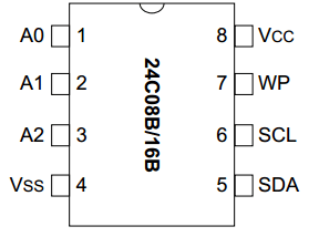
A0, A1, A2 are the address pins. The datasheet of this IC describes all.
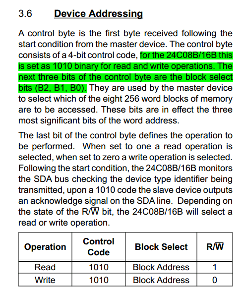
That means, if you want to read from the IC, then the control byte will be 1010 A0 A1 A2 1. I mean, if your IC’s address pins are (A0~A2) are all 0, then it will be: 1010 000 1 = 0xA1. Similarly, if you want to write, then it will be 0xA0. Now, let’s code for it.
mikroC code:
// LCD module connections
sbit LCD_RS at RB0_bit;
sbit LCD_EN at RB1_bit;
sbit LCD_D4 at RB2_bit;
sbit LCD_D5 at RB3_bit;
sbit LCD_D6 at RB4_bit;
sbit LCD_D7 at RB5_bit;

sbit LCD_RS_Direction at TRISB0_bit;
sbit LCD_EN_Direction at TRISB1_bit;
sbit LCD_D4_Direction at TRISB2_bit;
sbit LCD_D5_Direction at TRISB3_bit;
sbit LCD_D6_Direction at TRISB4_bit;
sbit LCD_D7_Direction at TRISB5_bit;
// End LCD module connections


// Software I2C connections
sbit Soft_I2C_Scl           at RC3_bit;
sbit Soft_I2C_Sda           at RC4_bit;
sbit Soft_I2C_Scl_Direction at TRISC3_bit;
sbit Soft_I2C_Sda_Direction at TRISC4_bit;
// End Software I2C connections


unsigned short read_EEPROM(unsigned short address)
{
  unsigned short r_data;
  Soft_I2C_Start();// issue I2C start signal
  Soft_I2C_Write(0xA0); // send byte via I2C (device address + W)
  Soft_I2C_Write(address);
  Soft_I2C_Start();
  Soft_I2C_Write(0xA1);
  r_data=Soft_I2C_Read(0);
  Soft_I2C_Stop();
  return(r_data);
}

void write_EEPROM(unsigned short address,unsigned short w_data)
{
  Soft_I2C_Start(); // issue I2C start signal
  Soft_I2C_Write(0xA0); // send byte via I2C (device address + W)
  Soft_I2C_Write(address);
  Soft_I2C_Write(w_data);
  Soft_I2C_Stop();
  Delay_ms(50);
}

int a=0;
char txt[]="00";
int k=0;

void main()
{
  TRISA = 0x0F;//RA0 input
  TRISB = 0x00;//all output
  TRISC = 0xFF;//all input
  ADCON1= 0x07;//all digital
  ADCON0= 0x00;//ADC OFF

  Soft_I2C_Init();           // Initialize Soft I2C communication
  Lcd_Init();                // Initialize LCD
  Lcd_Cmd(_LCD_CLEAR);       // Clear LCD display
  Lcd_Cmd(_LCD_CURSOR_OFF);  // Turn cursor off

  write_EEPROM(0,0);

 while(1)
 {
     a = 0;
     a = read_EEPROM(0);
     txt[0] = a/10 + 48;
     txt[1] = a%10 + 48;
     Lcd_Out(1,1,"Read from EEPROM");
     Lcd_Out(2,1,txt);

     Delay_ms(1000);
     write_EEPROM(0,k++);

     if(k>=99)k=0;

 }//while(1)
}//void main
As PIC16F73 does not have a master i2C, we used software i2C. There is no complex part in this code.
Result:
Conclusion:
This article was not a complete project, but it is more than that. It explores an option for MCU to use EEPROM. Anyway, if you feel that this article helps you, don’t forget to share it with others. Thanks.
Liked this article? Subscribe to our newsletter:
or,
Visit LabProjectsBD.com for more inspiring projects and tutorials.
Thank you!
This article may be helpful for you too: Not Enough ROM/RAM error with micro-controllers


1 Comment
R K Hamy · 15/12/2021 at 8:23 am
Many Thanks for the tutorial