Interfacing a 4×4 matrix keypad with STM32 microcontrollers is a common task in embedded systems development. This process involves configuring the GPIO pins, scanning the keypad using a multiplexing technique, and detecting any key presses based on the row and column combination. This article provides an overview of the process, along with a sample code snippet, to help you get started with integrating a keypad into your STM32-based projects.
⚠️Disclaimer:
Working with electricity involves serious risk. Ensure you have the necessary skills and take proper safety precautions before attempting any electrical projects. Proceed at your own risk — the author assumes no responsibility for any damage, injury, or issues resulting from the use or misuse of the information provided.
All content on this website is original and protected by copyright. Please do not copy or reproduce content without permission. While most of the resources shared here are open-source and freely accessible for your learning and benefit, your respect for our intellectual effort is appreciated.
If you find our tutorials helpful, consider supporting us by purchasing related materials or sharing our work — it helps keep the content flowing.
Need help or have questions? Leave a comment below — the author is always happy to assist!
Table of Contents
About the 4×4 matrix keypad:
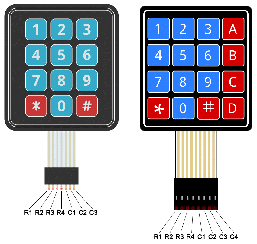
4 Rows and 4 Columns keypads are very common and popular. The working principle is very simple. Just check this diagram. It will be super easy to understand the concept.
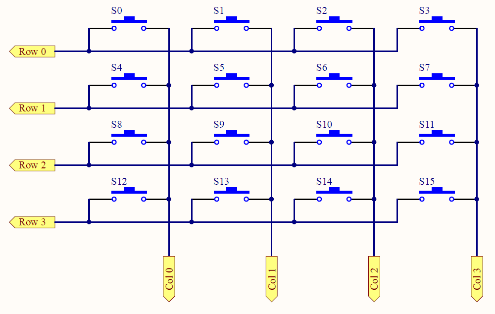
When any switch (s0 ~s15) is pressed, one of the pins from the Row and another one from the Column are connected. This will create conductivity through those two pins. And this is the concept of this type of keyboard.
Interface a 4×4 matrix keypad with an STM32 microcontroller:
To interface a 4×4 matrix keypad with an STM32 microcontroller, you can follow these general steps:
- Connect the keypad to the STM32 microcontroller using GPIO pins.
- Configure the GPIO pins on the STM32 microcontroller as inputs with pull-up resistors.
- Scan the keypad matrix by sequentially setting the columns as outputs and reading the rows as inputs.
- Detect any key press by checking which row and column combination produces a low signal.
- Convert the detected key press to a corresponding character or command, depending on the application.
Example code:
Here is an example code snippet to help you get started:
#include "stm32f4xx_hal.h"

#define ROW_1_Pin GPIO_PIN_0
#define ROW_2_Pin GPIO_PIN_1
#define ROW_3_Pin GPIO_PIN_2
#define ROW_4_Pin GPIO_PIN_3
#define COL_1_Pin GPIO_PIN_4
#define COL_2_Pin GPIO_PIN_5
#define COL_3_Pin GPIO_PIN_6
#define COL_4_Pin GPIO_PIN_7

GPIO_TypeDef* ROW_1_Port = GPIOA;
GPIO_TypeDef* ROW_2_Port = GPIOA;
GPIO_TypeDef* ROW_3_Port = GPIOA;
GPIO_TypeDef* ROW_4_Port = GPIOA;
GPIO_TypeDef* COL_1_Port = GPIOB;
GPIO_TypeDef* COL_2_Port = GPIOB;
GPIO_TypeDef* COL_3_Port = GPIOB;
GPIO_TypeDef* COL_4_Port = GPIOB;

void keypad_init(void)
{
  // Configure GPIO pins for keypad matrix
  GPIO_InitTypeDef GPIO_InitStruct = {0};
  GPIO_InitStruct.Pin = ROW_1_Pin | ROW_2_Pin | ROW_3_Pin | ROW_4_Pin;
  GPIO_InitStruct.Mode = GPIO_MODE_INPUT;
  GPIO_InitStruct.Pull = GPIO_PULLUP;
  HAL_GPIO_Init(ROW_1_Port, &GPIO_InitStruct);
  HAL_GPIO_Init(ROW_2_Port, &GPIO_InitStruct);
  HAL_GPIO_Init(ROW_3_Port, &GPIO_InitStruct);
  HAL_GPIO_Init(ROW_4_Port, &GPIO_InitStruct);

  GPIO_InitStruct.Pin = COL_1_Pin | COL_2_Pin | COL_3_Pin | COL_4_Pin;
  GPIO_InitStruct.Mode = GPIO_MODE_OUTPUT_PP;
  GPIO_InitStruct.Speed = GPIO_SPEED_FREQ_LOW;
  HAL_GPIO_Init(COL_1_Port, &GPIO_InitStruct);
  HAL_GPIO_Init(COL_2_Port, &GPIO_InitStruct);
  HAL_GPIO_Init(COL_3_Port, &GPIO_InitStruct);
  HAL_GPIO_Init(COL_4_Port, &GPIO_InitStruct);
}

char keypad_scan(void)
{
  char keys[4][4] = {{'1', '2', '3', 'A'},
                     {'4', '5', '6', 'B'},
                     {'7', '8', '9', 'C'},
                     {'*', '0', '#', 'D'}};

  for(int i = 0; i < 4; i++)
  {
    // Set current column as output and low
    switch(i)
    {
      case 0:
        HAL_GPIO_WritePin(COL_1_Port, COL_1_Pin, GPIO_PIN_RESET);
        HAL_GPIO_WritePin(COL_2_Port, COL_2_Pin, GPIO_PIN_SET);
        HAL_GPIO_WritePin(COL_3_Port, COL_3_Pin, GPIO_PIN_SET);
        HAL_GPIO_WritePin(COL_4_Port, COL_4_Pin, GPIO_PIN_SET);
        break;

      case 1:
        HAL_GPIO_WritePin(COL_1_Port, COL_1_Pin, GPIO_PIN_SET);
        HAL_GPIO_WritePin(COL_2_Port, COL_2_Pin, GPIO_PIN_RESET);
    HAL_GPIO_WritePin(COL_3_Port, COL_3_Pin, GPIO_PIN_SET);
    HAL_GPIO_WritePin(COL_4_Port, COL_4_Pin, GPIO_PIN_SET);
    break;

  case 2:
    HAL_GPIO_WritePin(COL_1_Port, COL_1_Pin, GPIO_PIN_SET);
    HAL_GPIO_WritePin(COL_2_Port, COL_2_Pin, GPIO_PIN_SET);
    HAL_GPIO_WritePin(COL_3_Port, COL_3_Pin, GPIO_PIN_RESET);
    HAL_GPIO_WritePin(COL_4_Port, COL_4_Pin, GPIO_PIN_SET);
    break;

  case 3:
    HAL_GPIO_WritePin(COL_1_Port, COL_1_Pin, GPIO_PIN_SET);
    HAL_GPIO_WritePin(COL_2_Port, COL_2_Pin, GPIO_PIN_SET);
    HAL_GPIO_WritePin(COL_3_Port, COL_3_Pin, GPIO_PIN_SET);
    HAL_GPIO_WritePin(COL_4_Port, COL_4_Pin, GPIO_PIN_RESET);
    break;
}

// Read current rows
if(HAL_GPIO_ReadPin(ROW_1_Port, ROW_1_Pin) == GPIO_PIN_RESET)
  return keys[0][i];
if(HAL_GPIO_ReadPin(ROW_2_Port, ROW_2_Pin) == GPIO_PIN_RESET)
  return keys[1][i];
if(HAL_GPIO_ReadPin(ROW_3_Port, ROW_3_Pin) == GPIO_PIN_RESET)
  return keys[2][i];
if(HAL_GPIO_ReadPin(ROW_4_Port, ROW_4_Pin) == GPIO_PIN_RESET)
  return keys[3][i];
}

return 0; // No key pressed
}

int main(void)
{
char key_pressed = 0;

// Initialize keypad
keypad_init();

while(1)
{
// Scan keypad and check for key press
key_pressed = keypad_scan();
if(key_pressed != 0)
{
  // Do something with the key press
  // ...
}
}

return 0;
}
This code defines the pins used to connect the keypad to the STM32 microcontroller and sets up the GPIO pins accordingly. It then defines a 4×4 matrix of characters that maps each row and column combination to a specific key. The keypad_scan() the function scans the keypad by sequentially setting each column as an output and reading each row as an input. It then detects any key press by checking which row and column combination produces a low signal and returns the corresponding character. The main() function simply calls keypad_scan() in a loop and does something with the detected key press.
Note that this is just an example code snippet, and you’ll need to modify it based on your specific requirements and the datasheet of your keypad. Some things you might need to consider include:
- The exact pin layout and connection scheme used by your keypad might be different from the one shown in this code.
- The debounce mechanism to prevent false key presses due to contact bounce.
- The method used to convert the detected key press to a corresponding character or command might involve a lookup table, a switch statement, or a more complex algorithm.
- The available memory and processing power on the STM32 microcontroller might limit the number of keys that can be detected and the speed at which the keypad can be scanned.
Conclusion:
Overall, interfacing a 4×4 matrix keypad with an STM32 microcontroller is a relatively straightforward process that involves configuring the GPIO pins, scanning the keypad using a multiplexing technique, and detecting any key press based on the row and column combination. With the appropriate code, you can easily integrate a keypad into your STM32-based project to enable user input and interaction.
If you’re new to working with microcontrollers or need additional guidance on how to interface a keypad with an STM32, there are many online resources and tutorials available that can help you get started. You can also consult the datasheets and documentation for your specific keypad and microcontroller to ensure proper connectivity and functionality.
Additionally, there are libraries and code examples available for popular keypads and microcontroller models that can simplify the process of interfacing them. These resources can save you time and effort in designing and testing your keypad interface and may provide useful insights and best practices for your project.
In conclusion, interfacing a 4×4 matrix keypad with an STM32 microcontroller is a valuable skill for anyone working with embedded systems, and can open up new possibilities for user input and interaction in your projects. With the right code and configuration, you can easily add keypad functionality to your STM32-based designs and create more engaging and interactive applications.
Read more on:
- GLCD 128×64 ST7920 interfacing with STM32
- How to interface a 16×2 LCD with an STM32
- How to interface ESP8266 with STM32
- How to interface DHT11 with STM32
- Designing a BMS with STM32
- STM32 Development Boards: A Guide for Beginners
Liked this article? Subscribe to our newsletter:
or,
Visit LabProjectsBD.com for more inspiring projects and tutorials.
Thank you!


0 Comments