Imagine controlling a relay circuit through a sleek web interface with the added layer of user authentication, all powered by NodeMCU v3. This project combines the convenience of remote control with the security of user verification, ensuring your setup remains both accessible and protected. Get ready to explore how we seamlessly integrate technology and security to enhance your IoT experience. Stay connected as we embark on this innovative journey together!
⚠️Disclaimer:
Working with electricity involves serious risk. Ensure you have the necessary skills and take proper safety precautions before attempting any electrical projects. Proceed at your own risk — the author assumes no responsibility for any damage, injury, or issues resulting from the use or misuse of the information provided.
All content on this website is original and protected by copyright. Please do not copy or reproduce content without permission. While most of the resources shared here are open-source and freely accessible for your learning and benefit, your respect for our intellectual effort is appreciated.
If you find our tutorials helpful, consider supporting us by purchasing related materials or sharing our work — it helps keep the content flowing.
Need help or have questions? Leave a comment below — the author is always happy to assist!
In our previous article, we introduced a relay switch on our website. Now, we’re taking it up a notch by adding essential security features. This project involves creating two button switches for toggling the relay, along with clear feedback indicators to display its status. Additionally, we’ll implement a robust security layer to safeguard against unauthorized access. If you’re keen on enhancing functionality while ensuring security, this project is tailor-made for you. Stay tuned as we delve into these exciting “Remote control with the security” developments together!
Table of Contents
Materials we need for our Remote control:
Hardware Required:
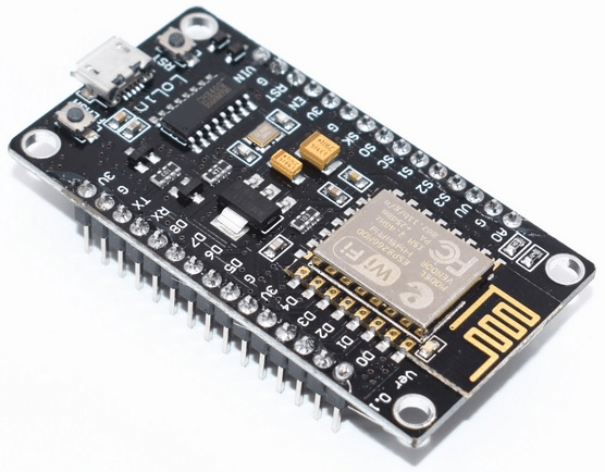
- NodeMCU v3 (ESP8266 development board)
- Relay module (ensure it can be driven by 3.3V logic)
- Jumper wires
- Breadboard and/or soldering equipment
- Power supply (USB cable for NodeMCU)
Software Required:
- Arduino IDE (for programming NodeMCU)
- Libraries:
- ESP8266WiFi (for WiFi connectivity)
- ESP8266WebServer (for handling web server requests)
- EEPROM (for storing credentials)
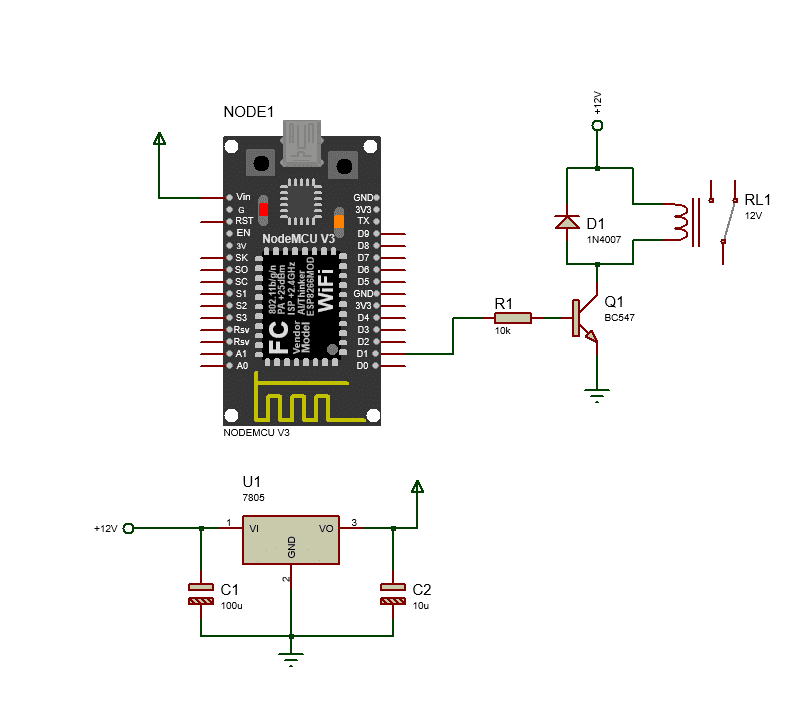
Circuit diagram of our Remote control:
There is no change in the circuit diagram. We’ll use our previous diagram for this.
Setting Up Arduino IDE
- Install ESP8266 Board in Arduino IDE:
- Go to Arduino IDE -> File -> Preferences.
- In the “Additional Board Manager URLs” field, add:
http://arduino.esp8266.com/stable/package_esp8266com_index.json. - Go to Tools -> Board -> Boards Manager, search for “esp8266” and install the package.
- Select NodeMCU 1.0 (ESP-12E Module) from Tools -> Board menu.
Arduino Code:
#include <ESP8266WiFi.h>
#include <ESP8266WebServer.h>
#include <EEPROM.h>

// WiFi credentials
const char* ssid = "SSID";
const char* password = "SSID_Password";

// Web server parameters
ESP8266WebServer server(80);
const char* http_username = "admin";//replace by yours
const char* http_password = "admin";//replace by yours

// Relay control pin
const int relayPin = D1; // GPIO pin where relay is connected
bool relayState = false; // Current state of the relay (initially OFF)

void setup() {
  // Initialize Serial port
  Serial.begin(115200);

  // Initialize relay pin as output
  pinMode(relayPin, OUTPUT);
  digitalWrite(relayPin, LOW); // Initialize relay as OFF

  // Connect to WiFi
  WiFi.begin(ssid, password);
  Serial.println("Connecting to WiFi...");
  while (WiFi.status() != WL_CONNECTED) {
    delay(1000);
    Serial.println("Connecting...");
  }
  Serial.println("WiFi connected!");
  Serial.print("IP address: ");
  Serial.println(WiFi.localIP());

  // Start server
  server.on("/", handleRoot); // Handle root URL
  server.on("/relay", handleRelay); // Handle relay control
  server.onNotFound(handleNotFound); // Handle not found pages

  server.begin();
  Serial.println("HTTP server started");
}

void loop() {
  server.handleClient(); // Handle client requests
}

// Handle root URL
void handleRoot() {
  if (!isAuthenticated()) {
    return server.requestAuthentication();
  }

  String html = "<html><head><style>";
  html += "body {";
  html += "  display: flex;";
  html += "  justify-content: center;";
  html += "  align-items: center;";
  html += "  height: 100vh;";
  html += "  margin: 0;";
  html += "}";
  html += ".container {";
  html += "  text-align: center;";
  html += "}";
  html += ".box {";
  html += "  border: 2px solid #ccc;";
  html += "  border-radius: 10px;";
  html += "  padding: 20px;";
  html += "  max-width: 400px;"; // Adjust box width if necessary
  html += "}";
  html += ".toggle-button {";
  html += "  display: inline-block;";
  html += "  width: 100px;";
  html += "  height: 50px;";
  html += "  text-align: center;";
  html += "  line-height: 50px;";
  html += "  font-size: 18px;";
  html += "  text-decoration: none;";
  html += "  margin: 10px;";
  html += "  cursor: pointer;";
  html += "  border: 2px solid #ccc;";
  html += "  border-radius: 25px;";
  html += "  background-color: #f1f1f1;";
  html += "  font-weight: bold;"; // Make the text bold
  html += "}";
  html += ".toggle-button.on {";
  html += "  background-color: #4CAF50;";
  html += "  color: white;";
  html += "}";
  html += ".toggle-button.off {";
  html += "  background-color: #f44336;";
  html += "  color: white;";
  html += "}";
  html += ".status-circle {";
  html += "  height: 200px;";
  html += "  width: 200px;";
  html += "  border-radius: 50%;";
  html += "  margin: 20px auto;"; // Center the circle horizontally
  html += "}";
  html += ".status-circle.on {";
  html += "  background-color: #4CAF50;";
  html += "}";
  html += ".status-circle.off {";
  html += "  background-color: #f44336;";
  html += "}";
  html += "</style></head><body>";
  html += "<div class='container'>";
  html += "<div class='box'>";
  html += "<h1>NodeMCU Relay Control</h1>";

  // Status Circle
  html += "<div class='status-circle";
  if (relayState) {
    html += " on";
  } else {
    html += " off";
  }
  html += "'></div>";

  // Toggle Button for Turning Relay ON
  html += "<a href='/relay?state=on' class='toggle-button";
  if (relayState) {
    html += " on";
  }
  html += "'>ON</a>";

  // Toggle Button for Turning Relay OFF
  html += "<a href='/relay?state=off' class='toggle-button";
  if (!relayState) {
    html += " off";
  }
  html += "'>OFF</a>";

  html += "</div>"; // Close box

  html += "</div>"; // Close container

  html += "</body></html>";

  server.send(200, "text/html", html);
}

// Handle relay control
void handleRelay() {
  if (!isAuthenticated()) {
    return server.requestAuthentication();
  }

  String state = server.arg("state");
  if (state == "on") {
    digitalWrite(relayPin, HIGH); // Turn relay ON
    relayState = true;
  } else if (state == "off") {
    digitalWrite(relayPin, LOW); // Turn relay OFF
    relayState = false;
  }

  handleRoot(); // Redirect to main page
}

// Handle not found pages
void handleNotFound() {
  if (!isAuthenticated()) {
    return server.requestAuthentication();
  }

  String message = "Page not found\n";
  message += "URI: ";
  message += server.uri();
  message += "\nMethod: ";
  message += (server.method() == HTTP_GET) ? "GET" : "POST";
  message += "\nArguments: ";
  message += server.args();
  message += "\n";

  server.send(404, "text/plain", message);
}

// Check if user is authenticated
bool isAuthenticated() {
  return server.authenticate(http_username, http_password);
}
Code Explanation:
- CSS Styling:
.container: Centers the entire content vertically and horizontally using flexbox..box: Adds a border, padding, and rounded corners to create a rectangular box around the content.max-widthis set to limit the width of the box..status-circle: Positioned inside.boxand centered horizontally (margin: 20px auto;). Increased size to 200px diameter for a larger circle.
- HTML Modifications:
- Moved the status circle inside the
.boxdiv, below the heading “NodeMCU Relay Control”. - Adjusted the spacing and alignment of the buttons to be center-aligned within the
.box.
- Moved the status circle inside the
Usage:
- Upload this updated code to your NodeMCU using the Arduino IDE.
- Connect to the NodeMCU’s WiFi network.
- Open a web browser and navigate to the IP address of your NodeMCU.
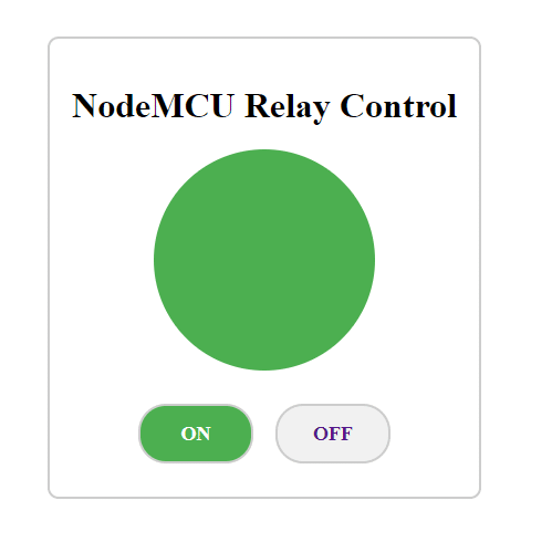
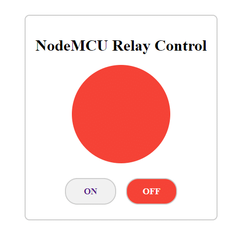
- You’ll see the status circle centered below the heading, inside a bordered box with smooth corners. The “ON” and “OFF” buttons will be centered and spaced appropriately below the status circle.
Result:
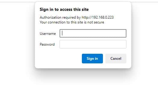
Once you browse the IP from any browser, a username and password popup will arrive. Insert ‘admin’ in both fields until you replace your username and password. This is for Remote control with the security feature. So that no one can access directly.
Then you will see this beautiful dashboard:
Conclusion:
Absolutely thrilling, isn’t it? This project has captured my interest. Imagine a smart IoT switch with built-in protections, paired with a beautifully designed and user-friendly dashboard. I can’t wait to see where this journey takes us next. Looking forward to exploring more exciting projects together. Stay connected and see you soon!
Read more:
- WiFi Controlled Scheduled Relay Using NodeMCU with Timed On/Off
- WiFi Controlled Relay Using NodeMCU v3: A Comprehensive Guide
Liked this article? Subscribe to our newsletter:
or,
Visit LabProjectsBD.com for more inspiring projects and tutorials.
Thank you!


0 Comments