Custom Industrial IoT Controller for Gas Odorizer Monitoring, Sensor Integration and Remote Control
Developing an electronic controller for industrial equipment is very different from developing a typical hobby IoT device.
The controller has to work reliably with external sensors, motors, pumps, relays and communication systems while also providing useful information to the operator.
This project was developed around that requirement: a custom IoT-enabled controller for an industrial gas odorizer system.
The objective was to bring several functions—including sensor monitoring, equipment feedback, local control and remote communication—into a single dedicated electronic controller.
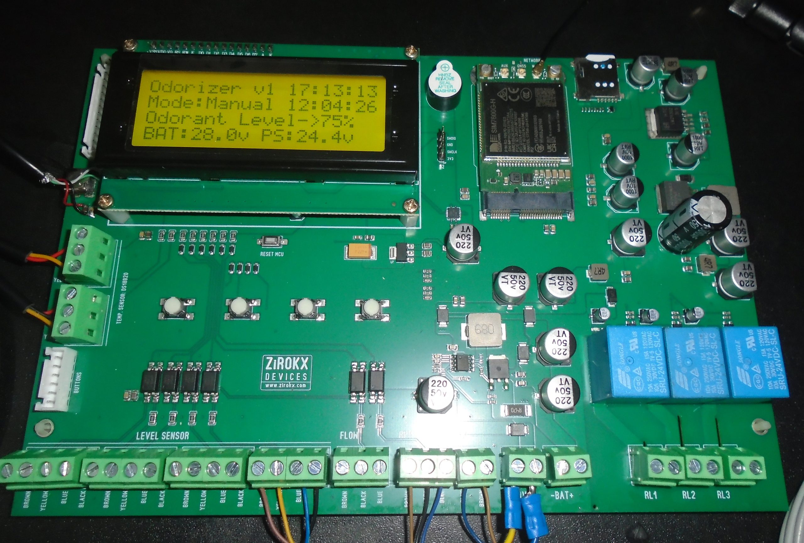
Table of Contents
Project Overview
The project started with a simple engineering requirement:
Build a dedicated electronic controller that can monitor and control an odorizer system while providing local information and remote IoT connectivity.
Instead of using several independent modules, the system was designed around a dedicated PCB.
The resulting controller combines:
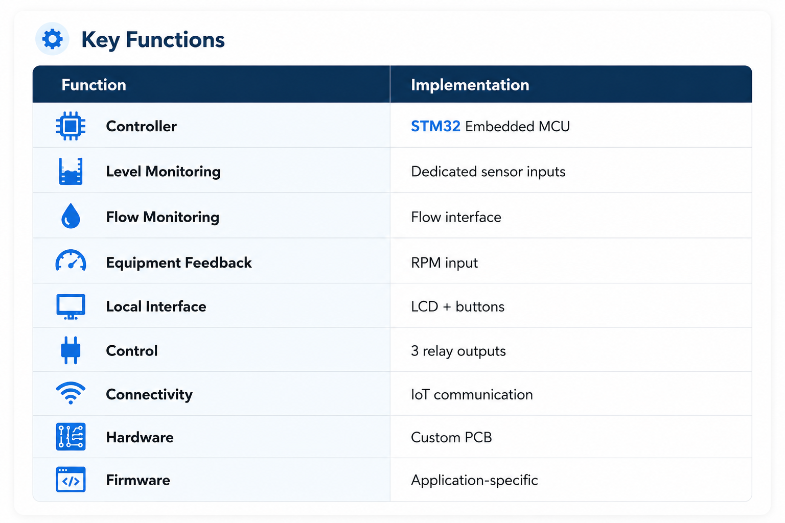
- Embedded microcontroller
- IoT communication
- LCD display
- Push-button interface
- Level sensor inputs
- Flow monitoring
- RPM feedback
- Relay outputs
- Power-management circuits
- External field connections
- Embedded firmware
The final PCB is therefore not just an IoT communication board. It is the main electronic interface between the physical odorizer equipment and the monitoring system.
Why an IoT Controller?
An industrial machine can operate perfectly well with a local controller, but remote installations create another problem.
A technician may need to know:
- Is the system running?
- Is the pump operating?
- Is there sufficient odorant?
- Is flow being detected?
- Is the equipment responding correctly?
- Has a fault occurred?
- Is the controller communicating?
Without remote monitoring, many of these questions require someone to physically inspect the equipment.
The purpose of adding IoT connectivity is to make this information available remotely.
The controller therefore has two important sides:
Local operation
and
Remote monitoring
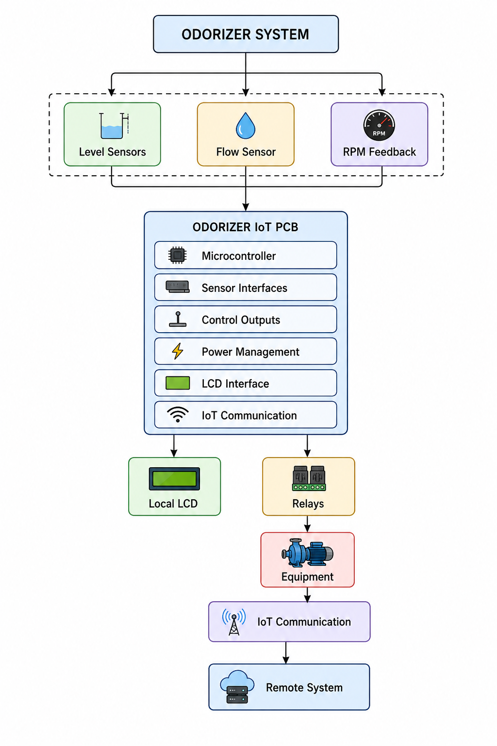
System Architecture
The overall architecture can be represented as:
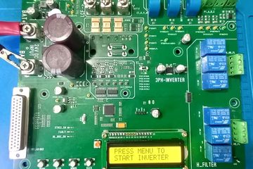
The Controller PCB
The heart of the system is a custom-designed PCB integrating the major electronic functions into one board.
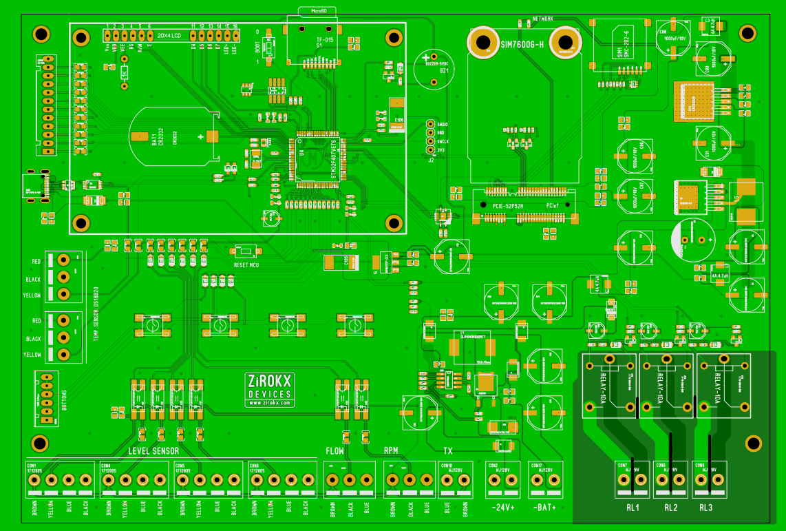
The board includes:
- Embedded microcontroller
- IoT communication module
- Level sensor interfaces
- Flow sensor interface
- RPM feedback input
- Relay outputs
- LCD interface
- Push-button controls
- Power-management circuitry
- Field wiring terminals
Rather than designing the electronics around a generic development board, the PCB was developed specifically for the application.
Sensor & Equipment Monitoring
A major part of the design is feedback monitoring.
The controller receives information from the equipment through multiple inputs, including level, flow and RPM signals.
This allows the system to distinguish between a command being issued and the equipment actually responding.
For example:
Control command → Equipment → RPM/Flow feedback → Controller
This approach provides much more useful information for monitoring and troubleshooting than simply checking whether an output has been activated.
Local Control & Display
The controller includes a local LCD and physical buttons for field operation.
The display can provide information such as system status, sensor conditions, equipment feedback and communication status.
The three relay outputs provide interfaces for external equipment and can be assigned according to the application requirements.
This gives the system both:
Local operation
and
Remote monitoring
without requiring the operator to depend entirely on the IoT platform.
IoT Connectivity
The controller also provides connectivity for remote monitoring.
The basic data flow is:
Sensors → MCU → Data Processing → IoT Communication → Remote System
This allows important operating information to be accessed without requiring someone to be physically present at the equipment.
The IoT communication section can also be adapted to the communication requirements of the final installation.
PCB Design & Hardware Development
The PCB was designed with both electrical performance and practical installation in mind.
Particular attention was given to:
- Sensor and field connections
- Power distribution
- Controller and communication sections
- Relay interfaces
- PCB component placement
- Signal routing
- Connector accessibility
- Serviceability
- Clear PCB labeling
The board uses clearly marked field terminals for connections such as LEVEL SENSOR, FLOW, RPM, TX, BAT+ and relay outputs, making installation and troubleshooting easier.
Embedded Firmware
The hardware is supported by custom embedded firmware responsible for coordinating the complete system.
The firmware handles:
- Sensor acquisition
- Equipment feedback
- Relay control
- LCD operation
- Button inputs
- System status
- Fault conditions
- IoT communication
- Remote data transmission
The hardware and firmware were developed together so that the controller could be tailored to the actual operating requirements of the equipment.
From PCB to Working System
The development process can be summarized as:
Requirement → Circuit Design → PCB Layout → Prototype → Firmware → Hardware Testing → Equipment Integration → IoT Testing
This is an important part of custom electronics development.
A PCB that works on a workbench is not necessarily ready for an industrial application. The electronics have to work with the sensors, equipment, wiring, and operating conditions of the actual system.
Final Result
The result is a dedicated industrial IoT controller that brings together equipment monitoring, feedback, local operation and remote connectivity on a single application-specific platform.
The same development approach can be adapted for other industrial equipment where monitoring, control and remote communication are required.
If you are working on an electronic product, industrial machine, or IoT system and need a custom PCB or embedded controller, feel free to get in touch.



0 Comments