Hi, you can generate a pure sine wave just using an Op-Amp. It is very simple and can be used in many applications. In this article, we are going to learn how to generate a pure sine wave using an Op-Amp.
⚠️Disclaimer:
Working with electricity involves serious risk. Ensure you have the necessary skills and take proper safety precautions before attempting any electrical projects. Proceed at your own risk — the author assumes no responsibility for any damage, injury, or issues resulting from the use or misuse of the information provided.
All content on this website is original and protected by copyright. Please do not copy or reproduce content without permission. While most of the resources shared here are open-source and freely accessible for your learning and benefit, your respect for our intellectual effort is appreciated.
If you find our tutorials helpful, consider supporting us by purchasing related materials or sharing our work — it helps keep the content flowing.
Need help or have questions? Leave a comment below — the author is always happy to assist!
Table of Contents
How to generate pure sine and co-sine wave?
There are different ways to generate sine and cosine waves. But You can do it in one of the most simple ways. Just using an Op-Amp. Even you do not need any special one for this. Just use any general-purpose Op-Amp for this. 3 resistors and 3 capacitors will be enough for our “how to generate a pure sine wave using an Op-Amp” project.
Circuit diagram:

Circuit explanation:
Here all the capacitors are non-polar ceramic capacitors. You can change the values to change the frequency. Here a start button is connected to the proteus circuit only. You do not need to use it in a practical circuit.
The working concept is very simple. One Op-Amp (LM358) generates an output which is slowed by the capacitor again another Op-Amp helps in another slow movement of reference. Thus a sine wave is formed rather than a square wave. And due to capacitor phase shift, we get a cosine wave.
Simulation result:

While simulating in proteus, press the start button once. In a practical test, you do not need this.
You can read this article from our blog: How to make a Single Phase AC voltmeter using PIC16F76 & Capacitor power supply
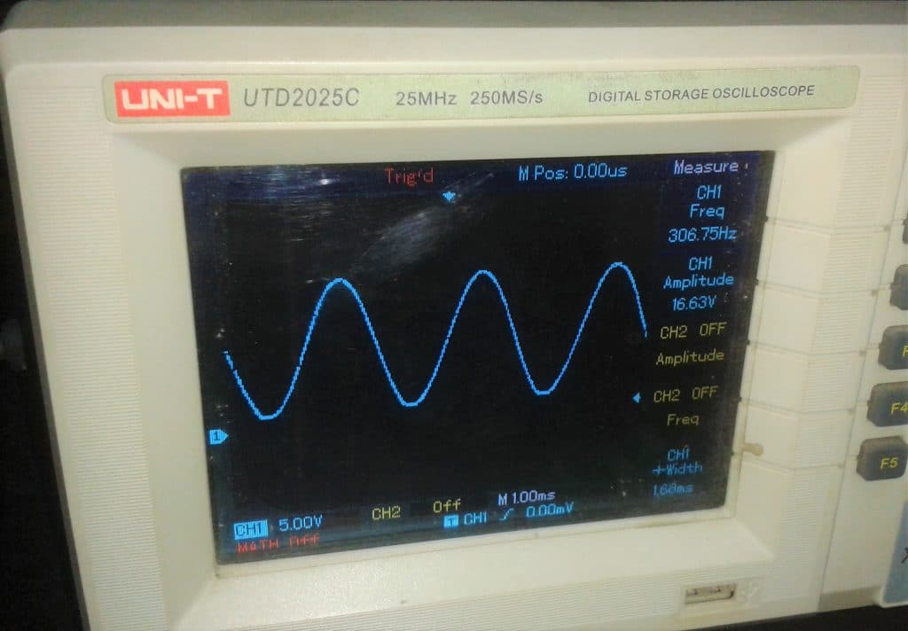
Practical test:
Practically, the circuit was arranged in a small project board and measured with an oscilloscope. Here I used variable resistors to test the effect of changing resistor values. You can do that too to do some research on a sine wave.
Conclusion:
This project was a very small one and interesting too. Who doesn’t like a sine wave? That’s why it was really interesting to me too. I hope you enjoyed the project and made one for yourself. Thank you, Enjoy!
Liked this article? Subscribe to our newsletter:
or,
Visit LabProjectsBD.com for more inspiring projects and tutorials.
Thank you!
Check this out: 5 coolest multimeters you can buTop 5 Digital Multimeters for beginners

7 Comments
Kingsley · 31/03/2022 at 3:12 pm
Good morning sir.
Please can this circuit be used to change the waveform of a square wave inverter using sg3524 into a pure sine wave output?
If yes, how can it be interfaced? Thank you as I sincerely awaits your positive response.
MKDas · 02/04/2022 at 12:50 pm
Good morning, No, you can not use SG3524/5 to make a sine wave inverter. You must use Sinusoidal PWM.
Md likhon · 25/04/2023 at 11:49 pm
hello sir , how are you?. Sir, I need 40khz frequency sine wave signal. I will use icl8038ccjd and 741 op-Amp . Your circuit should be like this.
MKDas · 26/04/2023 at 9:29 pm
741 will not support 40Khz. use something with low noise margin. ICL8038 works up to 100KHz, no problem. There is another article on ICL8038.
MKDas · 02/04/2022 at 12:54 pm
No, you can not use 3524/25 to make sine wave inverer. You have to use SPWM.
Ose · 07/09/2023 at 6:07 am
Thank you very much Sir. Please where can this circuit find practical application? Can it be used as an oscillator stage for an inverter? I await your response.
MKDas · 08/09/2023 at 8:42 pm
When the time comes, you’ll appreciate its value. Until then, it may seem superfluous.