A wattmeter is an useful meter to us. We can measure the power of the load with a wattmeter. You can buy this expensive meter but did you know that you can make one for yourself? In this article, we are going to learn how to make an AC Wattmeter using Arduino UNO.
⚠️Disclaimer:
Working with electricity involves serious risk. Ensure you have the necessary skills and take proper safety precautions before attempting any electrical projects. Proceed at your own risk — the author assumes no responsibility for any damage, injury, or issues resulting from the use or misuse of the information provided.
All content on this website is original and protected by copyright. Please do not copy or reproduce content without permission. While most of the resources shared here are open-source and freely accessible for your learning and benefit, your respect for our intellectual effort is appreciated.
If you find our tutorials helpful, consider supporting us by purchasing related materials or sharing our work — it helps keep the content flowing.
Need help or have questions? Leave a comment below — the author is always happy to assist!
Table of Contents
What is watt-meter and how it works?
A watt-meter does a complex job, measuring the power flowing through an electrical circuit. It simultaneously measures the voltage and current values and multiplies them to give power in watts.

For AC power, current and voltage may not be in phase, owing to the delaying effects of circuit inductance or capacitance. On an AC circuit, the deflection is proportional to the average instantaneous product of voltage and current, thus measuring active power, P=VI cos φ. Here, cosφ represents the power factor which shows that the power transmitted may be less than the apparent power obtained by multiplying the readings of a voltmeter and ammeter in the same circuit.
So to measure power we need to measure the voltage, current, and power factor for the AC circuit. And for the dc circuit, we can measure voltage and current and multiply them to get the power ratings.
How the voltage and current sensing circuit works?
Voltage Sensing:
For the AC circuit, we can use a step-down transformer to reduce the AC voltage (220V) into a lower (say 12V) range. A 220:12 step-down transformer can be used for this purpose. Then we have to use resistors to divide the voltages in a more suitable range for Arduino.
Current Sensing:
For current sensing, we need a CT or Current Transformer as the formal name. A CT needs to use a shunt resistor according to the CT properties or manufacturer’s suggestion.
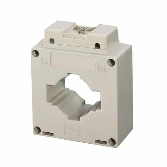
Industrial Panel type CT 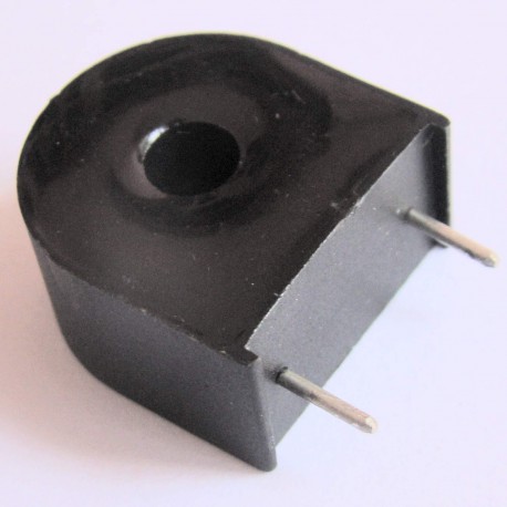
Through hole type for PCBs
Anyone can be used after considering the system properties.
How to utilize Arduino libraries for power measurement?
Arduino is an open-source device with lots of libraries to use. Among them, EmonLib is one of the most popular Arduino libraries for power measurement.
Sensing circuit configuration for EmonLib:
For EmonLib to work properly, we need to hang our sensing circuit from a 2.5V reference voltage as it calculates both positive and negative cycles.
For voltage reference, we can use simple voltage dividers like this:

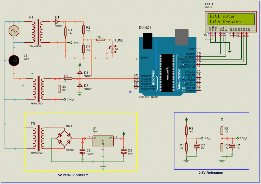
Circuit Diagram for our Watt-meter:
Here is the circuit diagram for our AC Wattmeter using Arduino UNO:

As you see, we hanged the voltage and current signal at 2.5V reference voltage. And for protection, we used two inverted diodes with the CT output. Any kind of CT you can use if you can calibrate in the code.
You can check: How to make a Single Phase AC voltmeter using PIC16F76 & Capacitor power supply too.
Testing and simulation:
As there is no physical data is used in proteus, we can’t get the actual results in proteus simulation. Although you can get something like this:
Coding:
Arduino UNO code for this project is:
#include "EmonLib.h"               // Include Emon Library
EnergyMonitor emon1;              // Create an instance
// include the library code:
#include <LiquidCrystal.h>  // initialize the library with the numbers of the interface pins
const int rs = 13, en = 12, d4 = 11, d5 = 10, d6 = 9, d7 = 8;
LiquidCrystal lcd(rs, en, d4, d5, d6, d7);
void setup()
{
  lcd.begin(16, 2); // set up the LCD’s number of columns and rows:
  emon1.voltage(0, 675.26, 1.7);   // Voltage: input pin, calibration, phase_shift
  emon1.current(1, 3.6);        // Current: input pin, calibration.
  lcd.setCursor(0, 0);
  lcd.print("Watt meter");
  lcd.setCursor(0, 1);
  lcd.print("With Arduino");
  delay(2000);
  lcd.clear();
}
void loop()
{
  emon1.calcVI(20, 2000);         // Calculate all. No.of half wavelengths (crossings), time-out
  emon1.serialprint();            // Print out  variable power factor)
  float powerFactor  = emon1.powerFactor;        //extract Power Factor into Variable
  lcd.setCursor(0, 0);
  lcd.print("PF:");
  lcd.setCursor(3, 0);
  lcd.print(powerFactor * 100);

  lcd.setCursor(9, 0);
  lcd.print("P:");
  lcd.setCursor(11, 0);
  lcd.print(emon1.realPower);

  lcd.setCursor(0, 1);
  lcd.print("V:");
  lcd.setCursor(2, 1);
  lcd.print(emon1.Vrms);

  lcd.setCursor(9, 1);
  lcd.print("I:");
  lcd.setCursor(11, 1);
  lcd.print(emon1.Irms);

  delay(3000);
  lcd.clear();

  lcd.setCursor(0, 0);
  lcd.print("P:");
  lcd.setCursor(2, 0);
  lcd.print(emon1.realPower);
  lcd.print("watt");

  lcd.setCursor(0, 1);
  lcd.print("P:");
  lcd.setCursor(2, 1);
  lcd.print(emon1.apparentPower);
  lcd.print("VA");
  delay(3000);
  lcd.clear();
}
Download the Arduino file from here.
Download the EmonLib library file from here.
PCB diagram:
The PCB design for our AC Wattmeter using Arduino UNO:
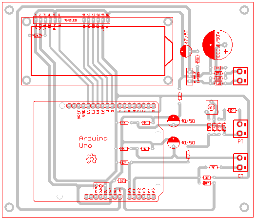
You can download the PCB files from here.
Practical testing:
This project was made and tested practically. The test result was ok. I didn’t find the image of the test project yet. Once I find it, I’ll share it here.
Conclusion:
The project was very simple and easy to understand. Using only a few parts you can now make a wattmeter for yourself.
I hope you enjoyed the project and will make one for yourself. Thanks, Enjoy!
Liked this article? Subscribe to our newsletter:
or,
Visit LabProjectsBD.com for more inspiring projects and tutorials.
Thank you!
Check this out: 5 coolest multimeters you can buy


12 Comments
Asimi · 02/08/2020 at 2:02 pm
Thank you sir. You have really gave a vital information. God bless you. Pls I would like you to post wattmeter measurements with PIC pls. God bless you and increased you in more knowledge, with more good health, long life and prosperity. You are a really God’s sent tutor with clean explanation, circuits diagram and some with simulation. We will be looking forward to seeing wattmeter measurements with PIC controller.
Mithun K. Das · 02/08/2020 at 2:14 pm
Hope to write on this in future. Thank you.
Chayan Mistry · 24/02/2021 at 3:58 am
Nice article dada
Mithun K. Das · 24/02/2021 at 7:32 am
Thanks
Chris · 14/04/2022 at 12:46 pm
Dear Sir
where do i have to connect 2.5 reference connection
Thank you
MKDas · 14/04/2022 at 4:33 pm
yes, you need to keep it.
Olly · 11/06/2022 at 10:17 pm
Good day sir,
You’ve done a great job here for us. May God increase your knowledge.
Please, my question is about the calibration. I mean the 2nd and 3rd line in setup of the code. Can you give the directions on the values in these two lines of the code.
In my own case, I’m using a 2000:1, 20A CT and I’m supplying 220v ac to the circuit.
Thanks in advance as I await your response.
MKDas · 13/06/2022 at 10:44 am
That is a library settings.
emon1.voltage(0, 675.26, 1.7); // Voltage: input pin, calibration, phase_shift
emon1.current(1, 3.6); // Current: input pin, calibration.
It has internal calculations. So you can change the calibration by testing few times. That will be better and practical.
Rafat bin mofidul · 17/12/2022 at 11:38 pm
sir,
You didn’t mention the rating of CT transformer you used .
MKDas · 18/12/2022 at 12:25 pm
Use what you have, then configure in the code.
liban abdi mohamed · 25/12/2024 at 9:00 pm
can you share how did you find these values 675.26 , 3.6 , voltage and current calibration in the above circuit design
MKDas · 27/12/2024 at 11:55 am
Please check that article. Maybe somewhere explained.