Irrigation is important for our farms whatever it is on large scale or on a small scale. Due to lack of rain and water flow, lots of crops damage each year. Even in your home plant pots need to do regular irrigation to keep your plants alive. In this article, we will learn to make an automated irrigation system that you can make within 30 minutes and set up the system in your plant and travel outside for weeks without any tension. So let’s start our Automatic Plant Irrigation using a PIC12F675 microcontroller.
⚠️Disclaimer:
Working with electricity involves serious risk. Ensure you have the necessary skills and take proper safety precautions before attempting any electrical projects. Proceed at your own risk — the author assumes no responsibility for any damage, injury, or issues resulting from the use or misuse of the information provided.
All content on this website is original and protected by copyright. Please do not copy or reproduce content without permission. While most of the resources shared here are open-source and freely accessible for your learning and benefit, your respect for our intellectual effort is appreciated.
If you find our tutorials helpful, consider supporting us by purchasing related materials or sharing our work — it helps keep the content flowing.
Need help or have questions? Leave a comment below — the author is always happy to assist!
Table of Contents
Effect of water in soil:
Dry soil is not conductive in manner. But a little bit of water in the soil makes it conductive in electronic behavior. That means, if we measure conductivity with a resistance meter, we’ll get high resistance in dry soil. But we’ll get low resistance in wet.

Working Concept of automated irrigation system:
So, all we need to do is to measure the soil conductivity. Based on conductivity we can identify if the soil is wet or dry. If the soil is dry, we will turn on a water pump which will supply water to the soil. When the soil gets wet, we’ll turn that water pump off. It is the concept of our project. Now we have to make everything in line sequentially.
What we need for this project?
For this project, we need these components/modules
- Soil moisture sensor
- A controller to control operation
- Water pump
- Switching device to turn the water pump on/off
- Plastic pipes.
Making a soil moisture sensor:
You can buy a soil moisture sensor or you can make one. It’s your choice. But I’ll suggest making one because there is no such rocket science behind a soil moisture sensor that you can not do yourself.
All you need two pieces of a copper wire what we use for coils/inductors.

Just cut in the length of 15-20 cm. Then remove the insulation using sandpaper or the bold side of a knife. Then cover the whole copper wire with solder lead using a soldering iron. This will reduce corrosion.
Solder connecting wire in one side of each copper wire and cover that with tapes. Just like a test probe of multi-meter.
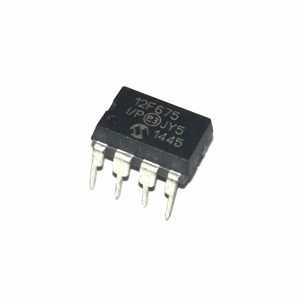
Select a controller to operate the circuit:
You can use Op-Amp for this purpose but I’ll suggest using a small microcontroller PIC16F675. A micro-controller will make the total job easy. Although an Op-Amp will work fine too. But little hassle may arise.
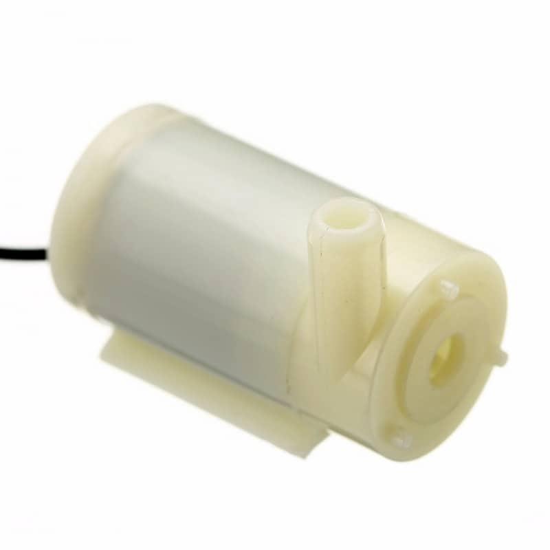
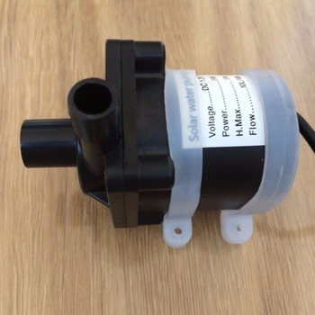
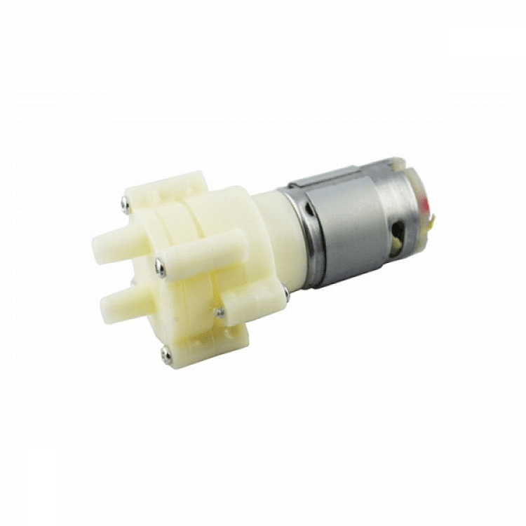
Select a Water pump for our project:
Any water pump you can select for this project. Anyone will work fine. Depending on your pump selection, the switching device will be changed.
Switching device for your pump:
Depending on your pump rating, a switching device can be selected. The most common device will be a relay. You can use common 12V relays for this purpose. But if your pump is highly rated, select a suitable relay or another device according to the pump ratings.

Collect some plastic pipes:
Collect some plastic pipes according to your pump in/out head’s diameter. Few meters of these pipes may work fine for your pump:

Now you’ve arranged most of the supplies and have got an idea of what you need. Let’s see the circuit diagram of this project.
Circuit diagram:
The circuit diagram of Automatic Plant Irrigation using a PIC12F675 is very easy. Here is the diagram:

Working principle:
As you can see, here we used the PIC12F675 micro-controller as our controller. A relay is used for switching purposes and test probes are connected to the AN0 (GP0 pin) of the micro-controller.
Using the ADC module of the micro-controller we can measure the voltage at the AN0/GP0 pin. This voltage will be high if the soil is dry and will be low if the soil is low. After a trial, we can select at which voltage we can set our set-points.
Transistor BC547 is used to operate the relay which is actually turning the pump on/off.
12V & 5V power supply is made with a transformer, bridge diode, capacitor, and voltage regulator LM7805.
Coding:
Here to code the micro-controller, I used mikroC Pro for PIC. You can download the file and use the hex only if you do not have the compiler.
/*******************************************************************************
*                    Program for, "Automatic Irrigation System"                *
*                       Code Written by_ Engr. Mithun K. Das                   *
*                          MCU: PIC12F675; X-Tal: 4MHz(in)                     *
*                                  Date: 03-10-2018                            *
*******************************************************************************/
unsigned int adc_rd=0,i=0;
#define        Wet_LED      GP5_bit
#define        Dry_LED      GP4_bit
#define        Pump         GP2_bit
void main()
{
 TRISIO = 0b00000001;// GP0 input only
 GPIO = 0x00;//clear port
 CMCON = 0x07;//Comparator off
 ANSEL = 0x01;//AN0 analog input
 ADCON0 = 0x01;//AN0 channel selected
 while(1)
 {
   for(i=0;i<10;i++)
   {
      adc_rd += ADC_Read(0);
      Delay_ms(100);
   }
   adc_rd/=10;//get avg value

   if(adc_rd<800)// wet?
   {
      Wet_LED = 1;// Wet LED on
      Dry_LED = 0; // Dry LED off
      Pump = 0;//pump off
   }
   else if(adc_rd>900)
   {
      Wet_LED = 0;// Wet LED off
      Dry_LED = 1; // Dry LED on
      Pump = 1;//pump on
   }

 }//while(1)
}//void main
Code is very simple and small. I think you can understand it easily.
You can download the mikroC file from here. or
You can download the .hex file from here.
PCB diagram for this project:
You can make the PCB for our Automatic Plant Irrigation using a PIC12F675. Here is the design.
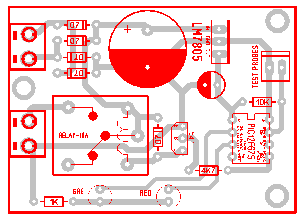
Download the PCB file from here.
Also, read PWM solar charge controller using PIC12F675 microcontroller.
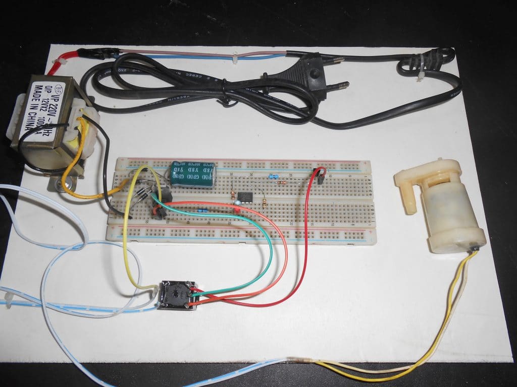
Practical testing:
I made this project in PCB. But at that time, I forgot to take some images of that project. So I rearranged the project on a project board here.
I hope you enjoyed the project and you made one for yourself. If you need any help, feel free to ask me. Thank you, Enjoy!
Liked this article? Subscribe to our newsletter:
or,
Visit LabProjectsBD.com for more inspiring projects and tutorials.
Thank you!
Check this out: 5 coolest multimeters you can buy


2 Comments
Godwin · 13/07/2021 at 7:18 pm
Hex file is no longer existing, please try and upload it again , sir
MKDas · 14/07/2021 at 1:34 pm
Download again. Total project file uploaded.