Seven Segment display is one of the most common LED/LCD-based displays which is used in many meters, clocks, info-display type devices. In this article, we’ll learn how to interface the Seven Segment display especially that one that has multiple digits in one line. The other name of this type of display is multiplexed 7segment display. Here we’ll learn how to use a 4×1 7segment display. So, let’s start our 7 Segment Display with PIC microcontroller.
⚠️Disclaimer:
Working with electricity involves serious risk. Ensure you have the necessary skills and take proper safety precautions before attempting any electrical projects. Proceed at your own risk — the author assumes no responsibility for any damage, injury, or issues resulting from the use or misuse of the information provided.
All content on this website is original and protected by copyright. Please do not copy or reproduce content without permission. While most of the resources shared here are open-source and freely accessible for your learning and benefit, your respect for our intellectual effort is appreciated.
If you find our tutorials helpful, consider supporting us by purchasing related materials or sharing our work — it helps keep the content flowing.
Need help or have questions? Leave a comment below — the author is always happy to assist!
Table of Contents
What is seven segment display?
To make a 7 Segment Display with PIC microcontroller, we need to know the Seven Segment First. The Seven Segment display is a set of 8(7+1) LEDs in blocks forming a digit and molded-in shape. Here, 7 LEDs are for digit/number display and 1 for dot(.) point. The internal configuration is something like this:
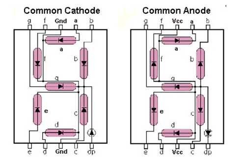
As you can see, in one segment LEDs are common by their cathode which is called CC or Common Cathode. And another one has anodes in common which are called CA or Common Anode. These two types of segments work almost similarly just the polarity of signals are different as like the LEDs.
What is multiplexed seven segment display?
In some 7segment blocks, there are several individual digits molded in one single piece of display. There may be 2,3,4 or even more digits in one line. These displays are internally connected, the 8 bits of the display are common for all of the displays in that line. Only the data bit which is equal to the digit numbers are kept, individual. That means, the internal connection is something like this:

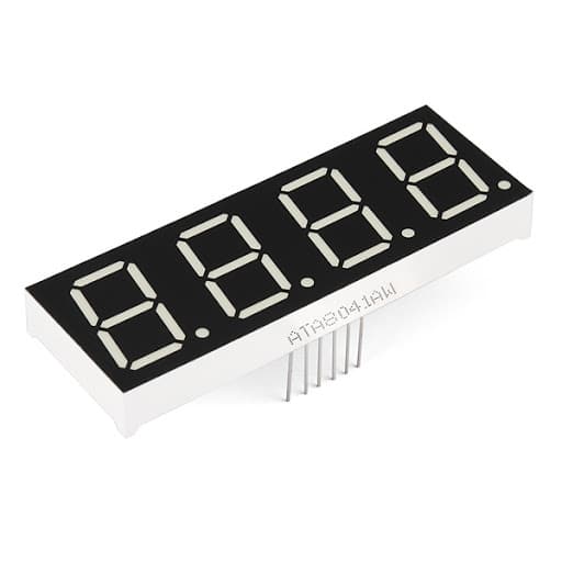
In practice, the display is a set of digits in one line like this one:
This way we can save pins to make our 7 Segment Display with PIC microcontroller project.
How to drive multiple 7segments ?
Like driving a single 7segment display, we need to generate a set of outputs for a digit and one data for each digit. Let take the segment as CC.
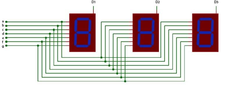
As you can see we have 7 sets of digit bits (a,b…g) and data bits of D1, D2, D3. Here if we set the digit array as 0x06 and D1 is connected to 0V/GND and D2, D3 are 5V then only digit 1 will display ‘1’, and the rest of the digits will show nothing. Again, if D1 and D3 are kept open/set to 5V and D2 to 0V/GND the second digit will display ‘1’.
As you can see when the 4th data is 0V, it is displaying the 4th digit only. The rest of the digits are kept off. Now you may ask how can we then display 4 digits as a 4 digit number same time? The answer is, we have a response time to anything. When an object moves from its place and came back in the same place before 0.25 seconds, our eye can not detect that change. That means, if we do the multiplexing of 4 individual digits within 0.25 seconds, our eye will see it as a 4 digit number.
You can check DC voltmeter using PIC microcontroller & Capacitor power supply.
Concept of multiplexing
So the concept of multiplexing, in this case, is we have to set the digits(a,b..g) of individual digit of a number at the same time the position of that digit will be set as the data. The same process for the second or third or more digits will be done sequentially. Whatever the data is we have to complete this process within 10ms. Then we’ll see a complete multi-digit number in the display.
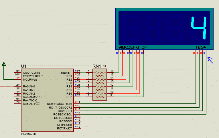
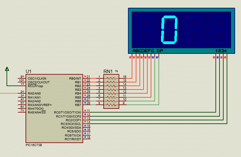
Circuit diagram:
Here is the circuit diagram of our 7 Segment Display with PIC microcontroller:

Coding:
Now we will do coding for this project with mikroC.
/*******************************************************************************
* Program for, "Seven Segment basic display"                                   *
* Program written by_ Engr. Mithun K. Das                                      *
* MCU:PIC16F73; Xtal:8MHz; mikroC pro for PIC v7.6.0                           *
* Date: 03-04-2020                                                             *
*******************************************************************************/


// array for segment digits, 0-9; CC;
char segment_array[]={0x3F,0x06,0x5B,0x4F,0x66,0x6D,0x7D,0x07,0x7F,0x6F};//CC_non dot

//pin declearation for digits
sbit digit0 at RC0_bit;
sbit digit1 at RC1_bit;
sbit digit2 at RC2_bit;
sbit digit3 at RC3_bit;

char digits[5];
void display_7segment(int number)
{
   digits[3]=number/1000u;      //store 1000th digit
   digits[2]=(number/100u)%10u; //store 100th digit
   digits[1]=(number/10u)%10u;  //store 10th digit
   digits[0]=(number/1u)%10u;   //store 1st digit
}

void InitTimer0()    //intterupt for 5ms timer ISR
{
  OPTION_REG     = 0x85;
  TMR0           = 100;
  INTCON         = 0xA0;
}

int position=0;
void Interrupt() iv 0x0004 ics ICS_AUTO
{
  if (TMR0IF_bit)
  {
    TMR0IF_bit   = 0;
    TMR0         = 100;

    digit0 = 1;
    digit1 = 1;
    digit2 = 1;
    digit3 = 1;
    if(position>3)position=0;

    PORTB = segment_array[digits[position]];
    if(position==3)
    {
        digit0 = 0;
        digit1 = 1;
        digit2 = 1;
        digit3 = 1;
    }
    else if(position==2)
    {
        digit0 = 1;
        digit1 = 0;
        digit2 = 1;
        digit3 = 1;
    }
    else if(position==1)
    {
        digit0 = 1;
        digit1 = 1;
        digit2 = 0;
        digit3 = 1;
    }
    else if(position==0)
    {
        digit0 = 1;
        digit1 = 1;
        digit2 = 1;
        digit3 = 0;
    }
    position++;
  }
}


unsigned int adc_value=0;
void main()
{
 TRISA=0xFF;//all input
 TRISB=0x00;//all output
 TRISC=0x00;//all output
 PORTB=0x00;
 PORTC=0x00;//clear ports
 ADCON1=0x00;
 ADCON0=0x01;//AN0 selected
 InitTimer0();//5ms timer
 while(1)
 {

    adc_value = ADC_Read(0);//read adc value
    display_7segment(adc_value); //print in display

 }
}//end
Code explanation:
// array for segment digits, 0-9; CC;
char segment_array[]={0x3F,0x06,0x5B,0x4F,0x66,0x6D,0x7D,0x07,0x7F,0x6F};//CC_non dot
In this block, we have an array for individual digits for the Common Cathode display. You can easily edit this value to whatever you like to see on display.

mikroC has this 7segment editing tool built in from where you can edit your number.
//pin declearation for digits
sbit digit0 at RC0_bit;
sbit digit1 at RC1_bit;
sbit digit2 at RC2_bit;
sbit digit3 at RC3_bit;
In this block, we simply set pins for each digit. It will help us in the next coding part.
void display_7segment(int number)
{
   digits[3]=number/1000u;      //store 1000th digit
   digits[2]=(number/100u)%10u; //store 100th digit
   digits[1]=(number/10u)%10u;  //store 10th digit
   digits[0]=(number/1u)%10u;   //store 1st digit
}
In this sub-function, we simply separating each digit of a number in the array. These arrays can be called individually and can be printed easily.
void Interrupt() iv 0x0004 ics ICS_AUTO
{
  if (TMR0IF_bit)
  {
    TMR0IF_bit   = 0;
    TMR0         = 100;

    digit0 = 1; //clear digits
    digit1 = 1;
    digit2 = 1;
    digit3 = 1;
    if(position>3)position=0;

    PORTB = segment_array[digits[position]];
    if(position==3)
    {
        digit0 = 0;
        digit1 = 1;
        digit2 = 1;
        digit3 = 1;
    }
    else if(position==2)
    {
        digit0 = 1;
        digit1 = 0;
        digit2 = 1;
        digit3 = 1;
    }
    else if(position==1)
    {
        digit0 = 1;
        digit1 = 1;
        digit2 = 0;
        digit3 = 1;
    }
    else if(position==0)
    {
        digit0 = 1;
        digit1 = 1;
        digit2 = 1;
        digit3 = 0;
    }
    position++;
  }
}
In this Interrupt Sub Routine, we are utilizing our 5ms time timer to print each digit sequentially. Here, Timer0 is used to call a 5ms timer interrupt. When we come back in this routine, we print the port array which is found from the digit array. And according to the position, data bits are switched. As we are programming for a common cathode (CC) display, so the digit will be activated when the data bit is 0. To clear digits, these data bits are set to 1.
adc_value = ADC_Read(0);//read adc value
display_7segment(adc_value); //print in display
And finally, in the while loop, we simply taking the ADC reading and displaying that value in our 7segment display.
Result:
In proteus, we can simulate this project 7 Segment Display with PIC microcontroller and check what it displays.
I hope you can now make your own multiplexed 7segment display for yourself. If you need any help feel free to ask me. Thank you, Enjoy!
Liked this article? Subscribe to our newsletter:
or,
Visit LabProjectsBD.com for more inspiring projects and tutorials.
Thank you!
Check this out: 5 coolest multimeters you can buy


0 Comments