Sometimes, we need to drive multiple displays in line. Sometimes we need to drive multiple numbers from one micro-controller. As micro-controller has a fixed number of pins so it is not possible to configure any circuit to drive 100 digits or even more 7-Segments. That is why we need to use shift registers. In this article, you will see how to use a shift register to interface multiple 7-segment with shift register 74HC595 a micro-controller.
⚠️Disclaimer:
Working with electricity involves serious risk. Ensure you have the necessary skills and take proper safety precautions before attempting any electrical projects. Proceed at your own risk — the author assumes no responsibility for any damage, injury, or issues resulting from the use or misuse of the information provided.
All content on this website is original and protected by copyright. Please do not copy or reproduce content without permission. While most of the resources shared here are open-source and freely accessible for your learning and benefit, your respect for our intellectual effort is appreciated.
If you find our tutorials helpful, consider supporting us by purchasing related materials or sharing our work — it helps keep the content flowing.
Need help or have questions? Leave a comment below — the author is always happy to assist!
Table of Contents
What is shift registers?
In digital circuits, a shift register is a cascade of flip flops, sharing the same clock, in which the output of each flip-flop is connected to the “data” input of the next flip-flop in the chain, resulting in a circuit that shifts by one position the “bit array” stored in it, “shifting in” the data present at its input and ‘shifting out’ the last bit in the array, at each transition of the clock input. _Wiki.
To know more about shift registers, please visit the wiki page here.
Shift registers are different in type. The most common ones are
- Serial in-parallel out
- Parallel in – Serial out
There are many types of shift registers, which can not be explained in short articles. Please do some research on this issue over the internet.
About 74HC595 Shift Register:
74HC595 is a serial into parallel-out with latch triggered tri-state shift register. This 16pin shift register is very common in use with a micro-controller as a port extender.
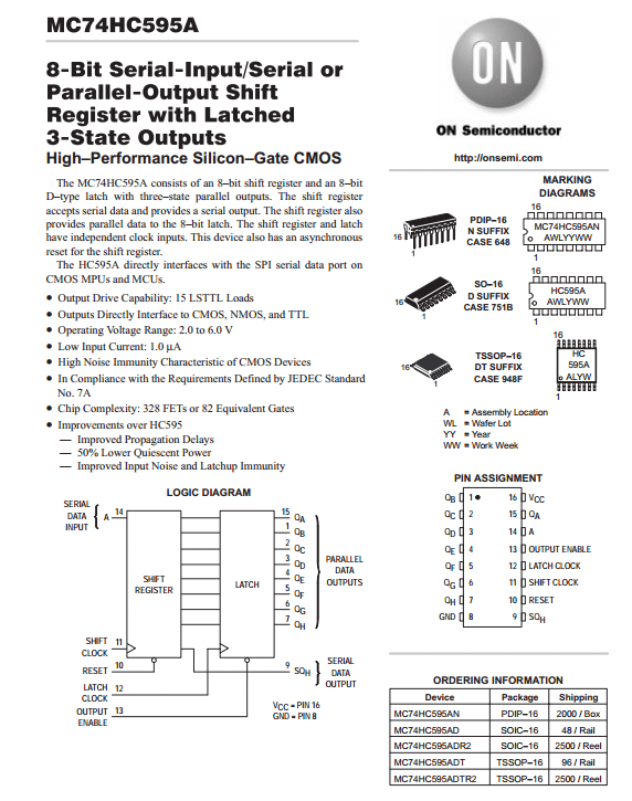

This SIPO shift register has a data input pin (A) where data can be loaded which is controlled by the shift clock. Then one latch clock shifts these data to its output pins according to the 8bit data pattern given serially at the data pin. Output Enable pin (!OE) is active low to enable output of that shift register. And the reset pin is also active low, connecting this reset pin to VDD will keep the operation going on. When we need more outputs, we just connect shift registers in cascade mode. For this, there is a data output (serial data out) pin. This pin will be then connected to the data input pin of the next shift register.
Cascading multiple shift registers
When we need more than 8bit output, we can just use more shift registers. These shift registers are then connected in cascade mode. Serial Data Output of the previous one will be connected to the data input of the next one. Keeping latch clock, shift clock common for each register, we can then get output from all of the shift registers according to our command.
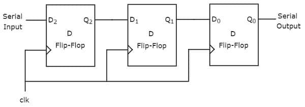
This is a simple cascade connection for the shift register. Here any type of shift register works almost in the same way. A common clock signal keeps all the shift registers synchronized.
Utilizing micro-controller’s feature to drive shift register:
Each micro-controller has some special feature built-in with it. In this project, we selected a PIC16F877A microcontroller. Smaller micro-controllers can be used if you wish to.

Here, in the MSSP module, we have an opportunity to use the SPI module. This Serial Peripheral Interface has dedicated communicating pins. RC5/SDO, RC4/SDI/SDA & RC3/SCL. Using these pins, we can easily interface any shift registers with a micro-controller.
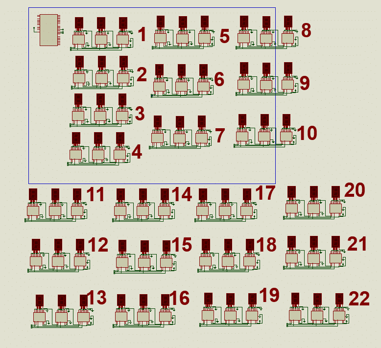
Circuit diagram:
Utilizing the cascade connecting facilities of 74HC595, we can draw our circuit diagram for driving multiple seven segments.

Here in this simulation, I did not use any resistor between the shift register and the 7-Segment display. You should use a resistor in a practical circuit. Better using a driver IC if the segment is big. ULN2003A will work fine.
Coding:
Here is the mikroC code for our multi-display project:
/*******************************************************************************
* Program for, Shift Register Display test for multiple digits                 *
* Program Written by_ Engr. Mithun_K_Das, [email protected]                  *
* MCU:PIC16F877A; X-Tal: 20MHz; mikroC pro for PIC v6.5.0                      *
* Date: 07-09-2017                                                             *
*******************************************************************************/

Digit_conversion(char digit)
{
   switch(digit)
   {
      case 0: digit = 0x3F; return digit;
      case 1: digit = 0x06; return digit;
      case 2: digit = 0x5B; return digit;
      case 3: digit = 0x4F; return digit;
      case 4: digit = 0x66; return digit;
      case 5: digit = 0x6D; return digit;
      case 6: digit = 0x7D; return digit;
      case 7: digit = 0x07; return digit;
      case 8: digit = 0x7F; return digit;
      case 9: digit = 0x6F; return digit;
   }
}

unsigned long number=0;
int digit=0;
void Disp_number(unsigned long value)
{
   digit = (value/1u)%10;
   SPI_Write(Digit_conversion(digit));
   digit = (value/10u)%10;
   SPI_Write(Digit_conversion(digit));
   digit = (value/100u)%10;
   SPI_Write(Digit_conversion(digit));
   digit = (value/1000u)%10;
   SPI_Write(Digit_conversion(digit));
   digit = (value/10000u)%10;
   SPI_Write(Digit_conversion(digit));
   digit = (value/100000u)%10;
   SPI_Write(Digit_conversion(digit));
   digit = (value/1000000u)%10;
   SPI_Write(Digit_conversion(digit));
   digit = (value/10000000u)%10;
}
void Update_display()
{
  PORTC.F6=1; //one latch clock
  PORTC.F6=0;
}

void InitTimer1()
{
    T1CON         = 0x31;
    TMR1IF_bit    = 0;
    TMR1H         = 0x0B;
    TMR1L         = 0xDC;
    TMR1IE_bit    = 1;
    INTCON        = 0xC0;
}

void Interrupt() iv 0x0004 ics ICS_AUTO
{
  if (TMR1IF_bit)
  {
      TMR1IF_bit = 0;
      TMR1H = 0x0B;
      TMR1L = 0xDC;
      //Enter your code here
      Disp_number(number);
      Update_display();
  }
}


void main()
{
  TRISC = 0x00;
  PORTC = 0x00;
  CMCON = 0x07;
  ADCON1 = 0x07;
  SPI1_Init_Advanced(_SPI_MASTER_OSC_DIV4, _SPI_DATA_SAMPLE_MIDDLE, _SPI_CLK_IDLE_LOW, _SPI_LOW_2_HIGH);
  InitTimer1();
  number = 2;
  while(1)
  {
      number+=number;
      Delay_ms(500);
      if(number>99999999)number=2;
  }

}
Code explanation:
Digit_conversion(char digit)
{
   switch(digit)
   {
      case 0: digit = 0x3F; return digit;
      case 1: digit = 0x06; return digit;
      case 2: digit = 0x5B; return digit;
      case 3: digit = 0x4F; return digit;
      case 4: digit = 0x66; return digit;
      case 5: digit = 0x6D; return digit;
      case 6: digit = 0x7D; return digit;
      case 7: digit = 0x07; return digit;
      case 8: digit = 0x7F; return digit;
      case 9: digit = 0x6F; return digit;
   }
}
In this part, digits are converted for 7-Segment. For Common Anode, you need to edit these values.
void Disp_number(unsigned long value)
{
   digit = (value/1u)%10;
   SPI_Write(Digit_conversion(digit));
   digit = (value/10u)%10;
   SPI_Write(Digit_conversion(digit));
   digit = (value/100u)%10;
   SPI_Write(Digit_conversion(digit));
   digit = (value/1000u)%10;
   SPI_Write(Digit_conversion(digit));
   digit = (value/10000u)%10;
   SPI_Write(Digit_conversion(digit));
   digit = (value/100000u)%10;
   SPI_Write(Digit_conversion(digit));
   digit = (value/1000000u)%10;
   SPI_Write(Digit_conversion(digit));
   digit = (value/10000000u)%10;
}
Here, the 8 figure number is split into individual digits and written to the shift register through the SPI module.
void Update_display()
{
  PORTC.F6=1; //one latch clock
  PORTC.F6=0;
}
This is generating a latch clock to throw the input of the shift register to its output pins. After writing all data serially, one latch clock reflects the inputs in output pins.
void Interrupt() iv 0x0004 ics ICS_AUTO
{
  if (TMR1IF_bit)
  {
      TMR1IF_bit = 0;
      TMR1H = 0x0B;
      TMR1L = 0xDC;
      //Enter your code here
      Disp_number(number);
      Update_display();
  }
}
You may not need to use ISR for the periodic updates, but here I used ISR to update the shift registers periodically. This helps to make the display more responsive. You can call these two functions serially to update the shift registers in the while loop.
Disp_number(number);
Update_display();
      number+=number;
      Delay_ms(500);
      if(number>99999999)number=2;
And finally, inside the while loop, this code is used to demonstrate the result in simulation quickly. You can use it in any format you need.
Test result:
In proteus, a simulation result shows how everything works. Check the video here:
If you understand the concept, you can add almost any number of shift registers and 7-Segment displays you need to. Here is another example where I elaborately used shift registers to interface several Seven Segment displays:
I’ll write another article on this one later. Anyway, I hope you are familiar with shift registers now. Can you make one for yourself now? I hope you can. If you can’t and are stuck in the middle, feel free to ask me. Thank you very much. Enjoy!
Liked this article? Subscribe to our newsletter:
or,
Visit LabProjectsBD.com for more inspiring projects and tutorials.
Thank you!
Check this out: 5 coolest multimeters you can buy


13 Comments
Laszlo Winkler · 20/05/2022 at 12:55 pm
Hello,
For me missing the series current limiting resistors from the IC (74HC595) outputs.
By the datasheet for driving LED need them.
If I were you I would have used DM13A – or equivalent IC (eg: MBI5024, STP16CPC26, ect..) because the output current can be set there.
.. and if you using PIC for the circuit than only one photoresistor and with PWM could control the brightness of the displays by the output enable (OE) pin.
Laszlo
MKDas · 20/05/2022 at 9:48 pm
simply use the resistance of 330 Ohm or 470 Ohm in each output pin.
Jatinder Bir Singh · 13/05/2023 at 12:19 pm
Can we use CD4015 in place of 74HC595?
MKDas · 13/05/2023 at 1:10 pm
no. both are different from each other.
Jatinder Bir Singh · 26/06/2023 at 7:20 pm
I wish to use this method to control 6x 3-digit SSD voltmeters with hi-lo settable info ,6-ADC inputs and 5-Switches for Hi-Lo settings Can you help me with?
MKDas · 02/07/2023 at 7:27 pm
You can use as many SSDs as you want with this method. Just follow the method
Jatinder Bir Singh · 13/05/2023 at 12:22 pm
If yes, do we need to make changes in Code?
MKDas · 13/05/2023 at 1:11 pm
adjust clock speed.
Sabah · 20/07/2023 at 5:08 am
v
can I get full complete code step by step or another one because this not work with me I dont what wrong ? I have 16 7segment digit to display 8 countdown counter I need your help me ….with my best wishes
MKDas · 22/07/2023 at 9:31 pm
This code is well tested. Check where you are making mistake.
Iftikhar Ahed · 11/06/2025 at 10:04 pm
The project works perfectly. However, one change is required in function
void Disp_number(unsigned long value).
add SPI_Write(Digit_conversion(digit)); at last. otherwise 7 ssd works not 8.
thanks for excellent tutorial
mohd azeem · 01/10/2023 at 5:36 pm
Dear Sir,
To make 24digit’s 7 segment count down timer, what changes have to be made in this code.
MKDas · 02/10/2023 at 9:30 pm
“If you understand the concept, you can add almost any number of shift registers and 7-Segment displays you need to”. Just try to catch the concept of expansion.