In this article, we will learn to make an AC voltmeter using Arduino UNO and 4×1 seven-segment display. If you learn this project clearly, you’ll be able to measure any AC voltage of your home. I hope you’ll make your own AC voltmeter using Arduino now.
⚠️Disclaimer:
Working with electricity involves serious risk. Ensure you have the necessary skills and take proper safety precautions before attempting any electrical projects. Proceed at your own risk — the author assumes no responsibility for any damage, injury, or issues resulting from the use or misuse of the information provided.
All content on this website is original and protected by copyright. Please do not copy or reproduce content without permission. While most of the resources shared here are open-source and freely accessible for your learning and benefit, your respect for our intellectual effort is appreciated.
If you find our tutorials helpful, consider supporting us by purchasing related materials or sharing our work — it helps keep the content flowing.
Need help or have questions? Leave a comment below — the author is always happy to assist!
Table of Contents
What is the difference in AC voltage measurement?
Like the DC voltmeter [check another article on DC voltmeter with Arduino] input voltage is not fixed in a point, it is alternating 50 times or 60 times per second. Whether you are in a 50Hz or 60Hz supply area, the measuring concept is the same.
If you measure like the DC voltmeter, you’ll get a fluctuating reading. That is why we need to follow a technique.
AC voltage measurement technique:
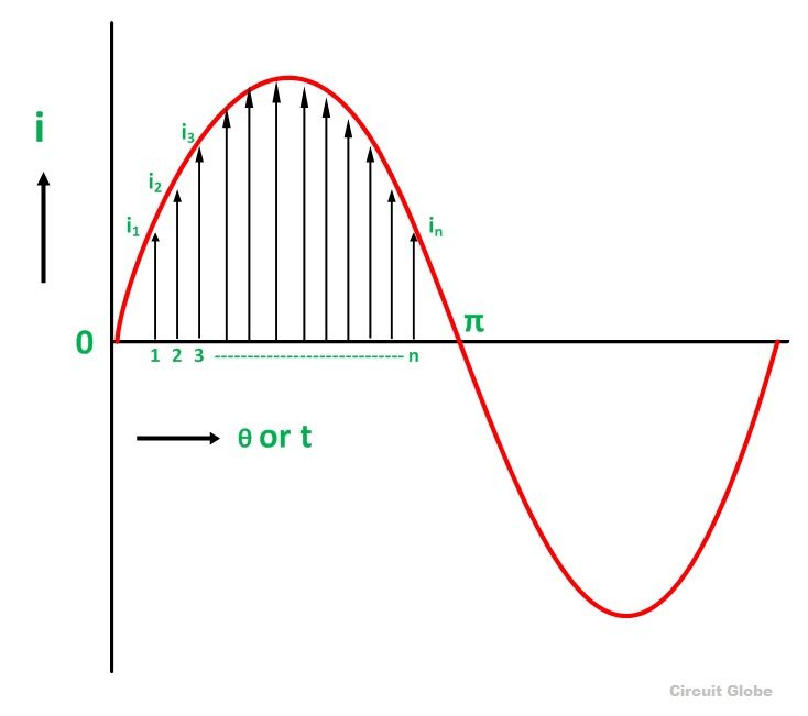
As the signal is alternating, so we can not measure with average reading only. But if we measure the peak points and calculate an average reading of some peak values, we can get the exact peak point result.
Now, we know how to get the RMS value from the peak value.
Vrms = Vpeak x 0.707
To find the peak point, we can use the Arduino peak point function. Also, we can do our own coding to find the peak point.
Circuit diagram:

Arduino Coding:
#include <TimerOne.h>
const char segment_pins[] = {13, 12, 11, 10, 9, 8, 7, 6}; //segments a to g
const char digit_pins[] = {5, 4, 3, 2}; // 4digits
const int digit_number = 4;//for 4 digit segment
byte dot_position;//set dot position from right side.
bool dot_point = true; // having dot or not, true = have dot, false = no dot.

const int segment_array[10][8] = // for common cathode segment only
{
  {HIGH, HIGH, HIGH, HIGH, HIGH, HIGH, LOW, LOW}, //0
  {LOW, HIGH, HIGH, LOW, LOW, LOW, LOW, LOW},     //1
  {HIGH, HIGH, LOW, HIGH, HIGH, LOW, HIGH, LOW},  //2
  {HIGH, HIGH, HIGH, HIGH, LOW, LOW, HIGH, LOW},  //3
  {LOW, HIGH, HIGH, LOW, LOW, HIGH, HIGH, LOW},   //4
  {HIGH, LOW, HIGH, HIGH, LOW, HIGH, HIGH, LOW},  //5
  {HIGH, LOW, HIGH, HIGH, HIGH, HIGH, HIGH, LOW}, //6
  {HIGH, HIGH, HIGH, LOW, LOW, LOW, LOW, LOW},    //7
  {HIGH, HIGH, HIGH, HIGH, HIGH, HIGH, HIGH, LOW},//8
  {HIGH, HIGH, HIGH, HIGH, LOW, HIGH, HIGH, LOW}, //9
};


void int_sev_segment()
{
  for (int k = 0; k < 8; k++)
  {
    pinMode(segment_pins[k], OUTPUT);//I/O settings
  }
  for (int k = 0; k < digit_number; k++)
  {
    pinMode(digit_pins[k], OUTPUT);//I/O settings
  }
  for (int k = 0; k < 8; k++)
  {
    digitalWrite(segment_pins[k], LOW);//keep low
  }
  for (int k = 0; k < digit_number; k++)
  {
    digitalWrite(digit_pins[k], HIGH);//keep high = disable segments (CC)
  }
  Timer1.initialize(5000);//5000us = 5ms
  Timer1.attachInterrupt(display_segment);
}


char digits[5];
void display_7segment(int number, byte dot)
{
  digits[3] = number / 1000u;//extract 1000th digit
  digits[2] = (number / 100u) % 10u;//extract 100th digit
  digits[1] = (number / 10u) % 10u;//extract 10th digit
  digits[0] = (number / 1u) % 10u;//extract 1st digit
  dot_position = dot;
}


int digit_position = 0;
void display_segment(void) // called periodically using timer interrupt
{
  for (int k = 0; k < digit_number; k++)
  {
    digitalWrite(digit_pins[k], HIGH);//reset digit pins
  }
  if (digit_position > 3)digit_position = 0;

  for (int k = 0; k < 8; k++) //print the a to g segment pins
  {
    digitalWrite(segment_pins[k], segment_array[digits[digit_position]][k]);
    if (digit_position == dot_position && dot_point == true)
    {
      digitalWrite(segment_pins[7], HIGH);//print dot point
    }
  }

  if (digit_position == 3)
  {
    digitalWrite(digit_pins[0], LOW);
    digitalWrite(digit_pins[1], HIGH);
    digitalWrite(digit_pins[2], HIGH);
    digitalWrite(digit_pins[3], HIGH);
  }
  else if (digit_position == 2)
  {
    digitalWrite(digit_pins[0], HIGH);
    digitalWrite(digit_pins[1], LOW);
    digitalWrite(digit_pins[2], HIGH);
    digitalWrite(digit_pins[3], HIGH);
  }
  else if (digit_position == 1)
  {
    digitalWrite(digit_pins[0], HIGH);
    digitalWrite(digit_pins[1], HIGH);
    digitalWrite(digit_pins[2], LOW);
    digitalWrite(digit_pins[3], HIGH);
  }
  else if (digit_position == 0)
  {
    digitalWrite(digit_pins[0], HIGH);
    digitalWrite(digit_pins[1], HIGH);
    digitalWrite(digit_pins[2], HIGH);
    digitalWrite(digit_pins[3], LOW);
  }
  digit_position++;
}


long ac_voltage = 0;
unsigned int temp, maxpoint;
void setup()
{
  int_sev_segment();//initialize seven segment program
}

void loop()
{
  ac_voltage = 0; //clear previous result
  temp = 0;
  maxpoint = 0;
  for (int i = 0; i < 20; i++)
  {
    for(int m=0;m<1000;m++)
    {
      if(temp = analogRead(A0);temp>maxpoint)
      {
        maxpoint = temp;
      }
    }
    ac_voltage += maxpoint*3.79659;
  }
  ac_voltage /= 20; //get average value

  display_7segment(ac_voltage, 2); //display value of cnt, dot in position 1 from right side

}

// end
Like the previous post on DC voltmeter with Arduino UNO, here the only change is in the AC voltage measurement function.
  ac_voltage = 0; //clear previous result
  temp = 0;
  maxpoint = 0;
  for (int i = 0; i < 20; i++)
  {
    for(int m=0;m<1000;m++)
    {
      if(temp = analogRead(A0);temp>maxpoint)
      {
        maxpoint = temp;
      }
    }
    ac_voltage += maxpoint*3.79659;
  }
  ac_voltage /= 20; //get average value
Here, we are using our own function to find the peak point. Then we calculated the RMS value from that peak value. And finally, we are taking an average value of 20 readings.
ac_voltage = 0; //clear previous result
  temp = 0;
  maxpoint = 0;
  for (int i = 0; i < 10; i++)
  {
    for(int m=0;m<500;m++)
    {
      if(temp = analogRead(A0);temp>maxpoint)
      {
        maxpoint = temp;
      }
    }
    ac_voltage += maxpoint*3.79659;
  }
  ac_voltage /= 10; //get average value
Here, taking fewer samples will make the meter more responsive.
Simulation test result:
Conclusion:
In this project, you learned how to make an AC voltmeter that can measure low voltage AC with Arduino and Op-Amp circuits. The result is displayed in multiplexed Seven segment display. We tested the voltmeter in the simulation. This project is now ready for practical use.
Kindly select voltage divider resistors carefully to measure higher voltage. Proper selection can increase the resolution of our voltmeter.
But keep in mind that electricity is always dangerous. Do work at your own risk.
I hope, you enjoyed this project and now you can make one for yourself. If you are stuck in the middle and need help, just ask. I’ll try my best to help you. Thank you, Enjoy!
Liked this article? Subscribe to our newsletter:
or,
Visit LabProjectsBD.com for more inspiring projects and tutorials.
Thank you!
Check this out: 5 coolest multimeters you can buy


2 Comments
mitesh · 03/06/2023 at 3:51 pm
what is 3.79659?
MKDas · 03/06/2023 at 4:00 pm
Explained in that article.