A DC voltmeter is very common in electronics and needs to use in many systems as well. In this article, we are going to learn how to make a DC voltmeter with Arduino and Seven Segment display. If you learn this carefully, you’ll be able to make a voltmeter of any voltage range.
⚠️Disclaimer:
Working with electricity involves serious risk. Ensure you have the necessary skills and take proper safety precautions before attempting any electrical projects. Proceed at your own risk — the author assumes no responsibility for any damage, injury, or issues resulting from the use or misuse of the information provided.
All content on this website is original and protected by copyright. Please do not copy or reproduce content without permission. While most of the resources shared here are open-source and freely accessible for your learning and benefit, your respect for our intellectual effort is appreciated.
If you find our tutorials helpful, consider supporting us by purchasing related materials or sharing our work — it helps keep the content flowing.
Need help or have questions? Leave a comment below — the author is always happy to assist!
Table of Contents
Basic part of a voltmeter:
A voltmeter has a sensing component or device and a display to show the reading. Sensing components may consist of resistor voltage dividers, Analog to Digital Converter (ADC), and other associated devices. For a low-range voltmeter, we can use a resistor voltage divider with capacitor filters. Then we can sense the low voltage across the resistor and calculate the input voltage using voltage divider rules.
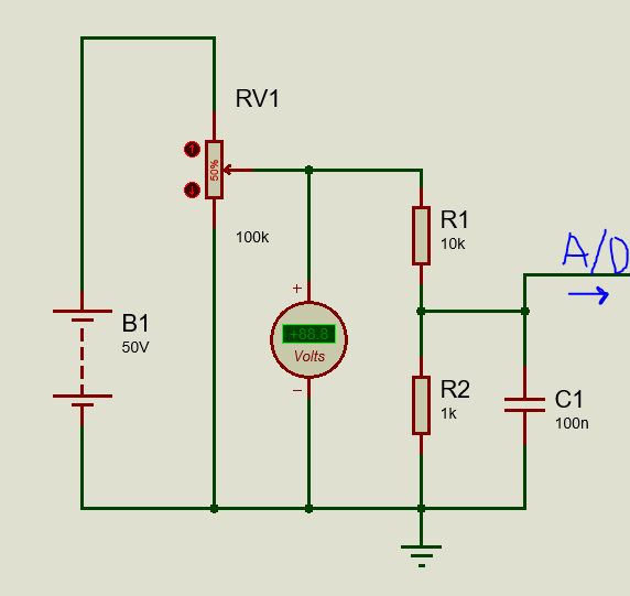
This is a resistor voltage divider circuit for voltage sensing purposes that will be used in our project. Here, C1 works as a noise filter here. If any noise is present in the sensing line, we can not detect exact voltage or our reading may result in an error. That is why we always need to use a capacitor as a noise filter.
As the display, we can use LCD display or Seven Segment displays. In this project, we’ll use the Seven Segment display.
Circuit diagram:

Arduino Coding:
#include <TimerOne.h>
const char segment_pins[] = {13, 12, 11, 10, 9, 8, 7, 6}; //segments a to g
const char digit_pins[] = {5, 4, 3, 2}; // 4digits
const int digit_number = 4;//for 4 digit segment
byte dot_position;//set dot position from right side.
bool dot_point = true; // having dot or not, true = have dot, false = no dot.

const int segment_array[10][8] = // for common cathode segment only
{
  {HIGH, HIGH, HIGH, HIGH, HIGH, HIGH, LOW, LOW}, //0
  {LOW, HIGH, HIGH, LOW, LOW, LOW, LOW, LOW},     //1
  {HIGH, HIGH, LOW, HIGH, HIGH, LOW, HIGH, LOW},  //2
  {HIGH, HIGH, HIGH, HIGH, LOW, LOW, HIGH, LOW},  //3
  {LOW, HIGH, HIGH, LOW, LOW, HIGH, HIGH, LOW},   //4
  {HIGH, LOW, HIGH, HIGH, LOW, HIGH, HIGH, LOW},  //5
  {HIGH, LOW, HIGH, HIGH, HIGH, HIGH, HIGH, LOW}, //6
  {HIGH, HIGH, HIGH, LOW, LOW, LOW, LOW, LOW},    //7
  {HIGH, HIGH, HIGH, HIGH, HIGH, HIGH, HIGH, LOW},//8
  {HIGH, HIGH, HIGH, HIGH, LOW, HIGH, HIGH, LOW}, //9
};


void int_sev_segment()
{
  for (int k = 0; k < 8; k++)
  {
    pinMode(segment_pins[k], OUTPUT);//I/O settings
  }
  for (int k = 0; k < digit_number; k++)
  {
    pinMode(digit_pins[k], OUTPUT);//I/O settings
  }
  for (int k = 0; k < 8; k++)
  {
    digitalWrite(segment_pins[k], LOW);//keep low
  }
  for (int k = 0; k < digit_number; k++)
  {
    digitalWrite(digit_pins[k], HIGH);//keep high = disable segments (CC)
  }
  Timer1.initialize(5000);//5000us = 5ms
  Timer1.attachInterrupt(display_segment);
}


char digits[5];
void display_7segment(int number, byte dot)
{
  digits[3] = number / 1000u;//extract 1000th digit
  digits[2] = (number / 100u) % 10u;//extract 100th digit
  digits[1] = (number / 10u) % 10u;//extract 10th digit
  digits[0] = (number / 1u) % 10u;//extract 1st digit
  dot_position = dot;
}


int digit_position = 0;
void display_segment(void) // called periodically using timer interrupt
{
  for (int k = 0; k < digit_number; k++)
  {
    digitalWrite(digit_pins[k], HIGH);//reset digit pins
  }
  if (digit_position > 3)digit_position = 0;

  for (int k = 0; k < 8; k++) //print the a to g segment pins
  {
    digitalWrite(segment_pins[k], segment_array[digits[digit_position]][k]);
    if (digit_position == dot_position && dot_point == true)
    {
      digitalWrite(segment_pins[7], HIGH);//print dot point
    }
  }

  if (digit_position == 3)
  {
    digitalWrite(digit_pins[0], LOW);
    digitalWrite(digit_pins[1], HIGH);
    digitalWrite(digit_pins[2], HIGH);
    digitalWrite(digit_pins[3], HIGH);
  }
  else if (digit_position == 2)
  {
    digitalWrite(digit_pins[0], HIGH);
    digitalWrite(digit_pins[1], LOW);
    digitalWrite(digit_pins[2], HIGH);
    digitalWrite(digit_pins[3], HIGH);
  }
  else if (digit_position == 1)
  {
    digitalWrite(digit_pins[0], HIGH);
    digitalWrite(digit_pins[1], HIGH);
    digitalWrite(digit_pins[2], LOW);
    digitalWrite(digit_pins[3], HIGH);
  }
  else if (digit_position == 0)
  {
    digitalWrite(digit_pins[0], HIGH);
    digitalWrite(digit_pins[1], HIGH);
    digitalWrite(digit_pins[2], HIGH);
    digitalWrite(digit_pins[3], LOW);
  }
  digit_position++;
}


long dc_voltage = 0;
void setup()
{
  int_sev_segment();//initialize seven segment program
}

void loop()
{
  dc_voltage = 0; //clear previous result
  for (int i = 0; i < 20; i++)
  {
    dc_voltage += analogRead(A0)*5.37;
  }
  dc_voltage /= 20; //get average value

  display_7segment(dc_voltage, 2); //display value of cnt, dot in position 1 from right side

}

// end
Here, the Multiplexed Seven Segment program is taken from my previous project, “How to interface multiplexed Seven Segment Display with Arduino with no library file in an easy way“. I’ll request to check that article first.
  dc_voltage = 0; //clear previous result
  for (int i = 0; i < 20; i++)
  {
    dc_voltage += analogRead(A0)*5.37;
  }
  dc_voltage /= 20; //get average value
Here, only dc voltage measurement function is additional. In this function, I just took an average result of 20 samples. You may ask where the 5.37 comes from. It comes from:
5/1023 x 11 x 100;
Here, 5 is from ADC reference voltage 5V; 1023 is ADC resolution of 10bit; 11 from resistor voltage divider and 100 is multiplied as we are displaying 2 digits after the decimal.
Result:
Conclusion:
In this article, we have seen how to make a DC voltmeter using Arduino UNO and Seven Segment. I hope you’ve learned the techniques and now you can make one for yourself.
By selecting proper resistors, you can read higher voltage. But always remember one thing, electricity is dangerous. Do work at your own risk.
I hope you enjoyed this project. If you need any help, feel free to ask. Thank you. Enjoy!
Liked this article? Subscribe to our newsletter:
or,
Visit LabProjectsBD.com for more inspiring projects and tutorials.
Thank you!
Check this out: 5 coolest multimeters you can buy


4 Comments
Max · 02/02/2022 at 6:07 am
Hi, I’m Max.
I have an issue with replicating this project. My circuit is wired with the Arduino exactly as on the diagram, my 4 digit 7 segment display lights up, but does not display any numbers except for garbage, no matter if I apply a voltage at the input end.
Could you please help with this? Any suggestions in rewiring or code modification would be much appreciated, thanks in advance!
Regards,
Max
MKDas · 02/02/2022 at 10:34 am
Seems like you are using the other type of segment. The code is for the common cathode segment only. You may be using common anode type.
Rafał · 03/06/2023 at 1:28 am
W kodzie trzeba zamienić stany anoda i katoda. Trzeba zmienić stan z niski na wysoki i wysoki na niski. Wtedy działa na wyświetlacz ze wspólną anoda 🙂
MKDas · 03/06/2023 at 3:59 pm
Translate in English please