In this article, we are going to learn how to make a high voltage AC voltmeter using Arduino and we are going to measure 2500V. Utilizing the technique shown here, we can even measure more than this range. So let’s start our High Voltage AC voltmeter.
⚠️Disclaimer:
Working with electricity involves serious risk. Ensure you have the necessary skills and take proper safety precautions before attempting any electrical projects. Proceed at your own risk — the author assumes no responsibility for any damage, injury, or issues resulting from the use or misuse of the information provided.
All content on this website is original and protected by copyright. Please do not copy or reproduce content without permission. While most of the resources shared here are open-source and freely accessible for your learning and benefit, your respect for our intellectual effort is appreciated.
If you find our tutorials helpful, consider supporting us by purchasing related materials or sharing our work — it helps keep the content flowing.
Need help or have questions? Leave a comment below — the author is always happy to assist!
Table of Contents
High voltage measurement technique:
Measuring high voltage is not safe for anyone. But if it needs to be done, then we must find a safe way to do the job. We should not measure high voltages keeping one terminal connected with the measuring instrument. Connecting with a common terminal increases the risk of getting an electric shock, burn, or fire. That is why isolation is required. Sometimes this isolation is done through high-valued resistors, sometimes with optocouplers. But in the DC circuit, we can use high-valued resistors in series to form isolation. Adding an Op-Amp circuit, the process becomes more sensitive and accurate. To make our High Voltage AC voltmeter, we need to understand this measurement circuit first.
Op-Amp based high voltage measurement circuit:
Most High Voltage AC voltmeter follows this circuit for measurement.
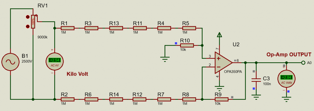
Here in this circuit, we use an Op-Amp (OPA350) and several resistors to make a floating or isolated voltage measuring circuit. The circuit simply measuring the voltage difference between two points. This differential amplifier circuit can be used in many types of measuring circuits where we can measure voltage differences of two points. Simple configuration and simple calculation.
Here, Gain = R9/(R2+R6+R7+R8)
Circuit diagram:
Here is the circuit diagram of our High Voltage AC voltmeter:
Arduino Coding:
Before reading the code, please check my other article about this, “How to make an AC voltmeter using Arduino UNO and 4×1 multiplexed Seven Segment display“. Then it will be easy to understand.
#include <TimerOne.h>
const char segment_pins[] = {13, 12, 11, 10, 9, 8, 7, 6}; //segments a to g
const char digit_pins[] = {5, 4, 3, 2}; // 4digits
const int digit_number = 4;//for 4 digit segment
byte dot_position;//set dot position from right side.
bool dot_point = false; // having dot or not, true = have dot, false = no dot.

const int segment_array[10][8] = // for common cathode segment only
{
  {HIGH, HIGH, HIGH, HIGH, HIGH, HIGH, LOW, LOW}, //0
  {LOW, HIGH, HIGH, LOW, LOW, LOW, LOW, LOW},     //1
  {HIGH, HIGH, LOW, HIGH, HIGH, LOW, HIGH, LOW},  //2
  {HIGH, HIGH, HIGH, HIGH, LOW, LOW, HIGH, LOW},  //3
  {LOW, HIGH, HIGH, LOW, LOW, HIGH, HIGH, LOW},   //4
  {HIGH, LOW, HIGH, HIGH, LOW, HIGH, HIGH, LOW},  //5
  {HIGH, LOW, HIGH, HIGH, HIGH, HIGH, HIGH, LOW}, //6
  {HIGH, HIGH, HIGH, LOW, LOW, LOW, LOW, LOW},    //7
  {HIGH, HIGH, HIGH, HIGH, HIGH, HIGH, HIGH, LOW},//8
  {HIGH, HIGH, HIGH, HIGH, LOW, HIGH, HIGH, LOW}, //9
};


void int_sev_segment()
{
  for (int k = 0; k < 8; k++)
  {
    pinMode(segment_pins[k], OUTPUT);//I/O settings
  }
  for (int k = 0; k < digit_number; k++)
  {
    pinMode(digit_pins[k], OUTPUT);//I/O settings
  }
  for (int k = 0; k < 8; k++)
  {
    digitalWrite(segment_pins[k], LOW);//keep low
  }
  for (int k = 0; k < digit_number; k++)
  {
    digitalWrite(digit_pins[k], HIGH);//keep high = disable segments (CC)
  }
  Timer1.initialize(5000);//5000us = 5ms
  Timer1.attachInterrupt(display_segment);
}


char digits[5];
void display_7segment(int number, byte dot)
{
  digits[3] = number / 1000u;//extract 1000th digit
  digits[2] = (number / 100u) % 10u;//extract 100th digit
  digits[1] = (number / 10u) % 10u;//extract 10th digit
  digits[0] = (number / 1u) % 10u;//extract 1st digit
  dot_position = dot;
}


int digit_position = 0;
void display_segment(void) // called periodically using timer interrupt
{
  for (int k = 0; k < digit_number; k++)
  {
    digitalWrite(digit_pins[k], HIGH);//reset digit pins
  }
  if (digit_position > 3)digit_position = 0;

  for (int k = 0; k < 8; k++) //print the a to g segment pins
  {
    digitalWrite(segment_pins[k], segment_array[digits[digit_position]][k]);
    if (digit_position == dot_position && dot_point == true)
    {
      digitalWrite(segment_pins[7], HIGH);//print dot point
    }
  }

  if (digit_position == 3)
  {
    digitalWrite(digit_pins[0], LOW);
    digitalWrite(digit_pins[1], HIGH);
    digitalWrite(digit_pins[2], HIGH);
    digitalWrite(digit_pins[3], HIGH);
  }
  else if (digit_position == 2)
  {
    digitalWrite(digit_pins[0], HIGH);
    digitalWrite(digit_pins[1], LOW);
    digitalWrite(digit_pins[2], HIGH);
    digitalWrite(digit_pins[3], HIGH);
  }
  else if (digit_position == 1)
  {
    digitalWrite(digit_pins[0], HIGH);
    digitalWrite(digit_pins[1], HIGH);
    digitalWrite(digit_pins[2], LOW);
    digitalWrite(digit_pins[3], HIGH);
  }
  else if (digit_position == 0)
  {
    digitalWrite(digit_pins[0], HIGH);
    digitalWrite(digit_pins[1], HIGH);
    digitalWrite(digit_pins[2], HIGH);
    digitalWrite(digit_pins[3], LOW);
  }
  digit_position++;
}


long ac_voltage = 0;
unsigned int temp, maxpoint;
void setup()
{
  int_sev_segment();//initialize seven segment program
}

void loop()
{
  ac_voltage = 0; //clear previous result
  temp = 0;
  maxpoint = 0;
  for (int i = 0; i < 10; i++)
  {
    for(int m=0;m<500;m++)
    {
      if(temp = analogRead(A0);temp>maxpoint)
      {
        maxpoint = temp;
      }
    }
    ac_voltage += maxpoint*2.455;
  }
  ac_voltage /= 10; //get average value

  display_7segment(ac_voltage, 2); //display value of cnt, dot in position 1 from right side

}

// end
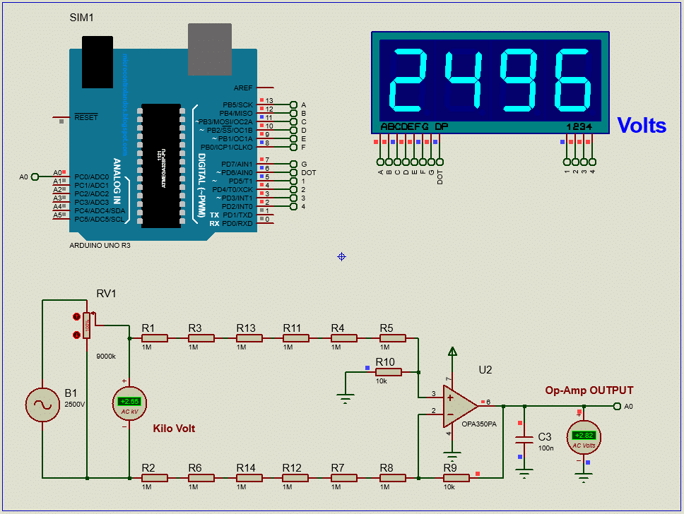
Test Result:
The test result of our High Voltage AC voltmeter:
Conclusion:
In this project, you learned how to make an AC voltmeter that can measure 2500V (!!!) with Arduino and Op-Amp circuit. The result is displayed in multiplexed Seven segment display. We tested the voltmeter in the simulation. This project is now ready for practical use.
Kindly select voltage divider resistors carefully to measure higher voltage. Proper selection can increase the resolution of our voltmeter.
But keep in mind that electricity is always dangerous. Do work at your own risk.
I hope, you enjoyed this project and now you can make one for yourself. If you are stuck in the middle and need help, just ask. I’ll try my best to help you. Thank you, Enjoy!
Liked this article? Subscribe to our newsletter:
or,
Visit LabProjectsBD.com for more inspiring projects and tutorials.
Thank you!
Check this out: 5 coolest multimeters you can buy


8 Comments
djalltra · 20/10/2020 at 11:11 am
can you please make the mikroc version
Mithun K. Das · 20/10/2020 at 2:13 pm
A similar project is posted with mikroC. Please check.
djallra · 21/10/2020 at 10:51 am
i notice you did not connect a 2.5v offset to this circuit why so?
Mithun K. Das · 22/10/2020 at 5:52 am
Yes, but it depends on your required result what you want. Make this circuit and simulate with and without 2.5V ref connection. Observe the output signals. I hope you’ll get the point.
Djalltra · 18/05/2022 at 12:55 pm
Hi based on the schematic the gain calculated does Not correspond as you have omitted R14 & R13 that means RF/RT=10k/4M=0.0025 multiplying by 1000 to remove the zeros but why the 2.455
MKDas · 18/05/2022 at 4:08 pm
Well, MCU can not print floating on the segment. SO, we multiplied it to use the digits after the dot.
Nayem · 16/07/2025 at 3:47 am
How much time required for only voltage calculation?
MKDas · 16/07/2025 at 12:21 pm
Never measured it.