In this article, we will discuss DC Current measurement using Shunt. Measuring current sometimes becomes very necessary in electronics circuits. We can measure DC current using current sensors or by using simple shunt resistors. In this article, I’m going to discuss DC current measurement techniques and different circuits for this purpose.
⚠️Disclaimer:
Working with electricity involves serious risk. Ensure you have the necessary skills and take proper safety precautions before attempting any electrical projects. Proceed at your own risk — the author assumes no responsibility for any damage, injury, or issues resulting from the use or misuse of the information provided.
All content on this website is original and protected by copyright. Please do not copy or reproduce content without permission. While most of the resources shared here are open-source and freely accessible for your learning and benefit, your respect for our intellectual effort is appreciated.
If you find our tutorials helpful, consider supporting us by purchasing related materials or sharing our work — it helps keep the content flowing.
Need help or have questions? Leave a comment below — the author is always happy to assist!
Table of Contents
DC current sensing techniques:
Based on different circuit configurations and the use of current sensing devices, we can divide the DC current sensing techniques into 2 types:
- Shunt resistor based sensing
- Hall effect sensor based sensing
Now we can get different configurations in circuits. In shunt resistor-based circuits, sometimes the shunt resistor is common with measuring circuits. But sometimes, the sensing shunt resistor is not connected with the measuring circuit even sometimes the source is floating. Based on these two configurations we can divide shunt resistor based sensing into 2 parts:
- Low side shunt resistor based sensing
- High side or floating shunt resistor based sensing
On the other type with hall effect sensor-based current sensing, we can find another similar type named ‘Magneto-resistive current sensor’ but it not so popular in DC current sensing at a small range.
Now, here in this article, we will discuss the shunt resistor-based current sensing. In the other article, I’ll cover the hall effect-based current sensing techniques.
Shunt resistor based current sensing:
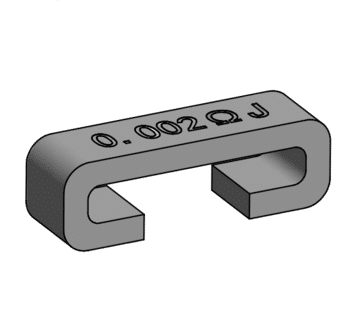
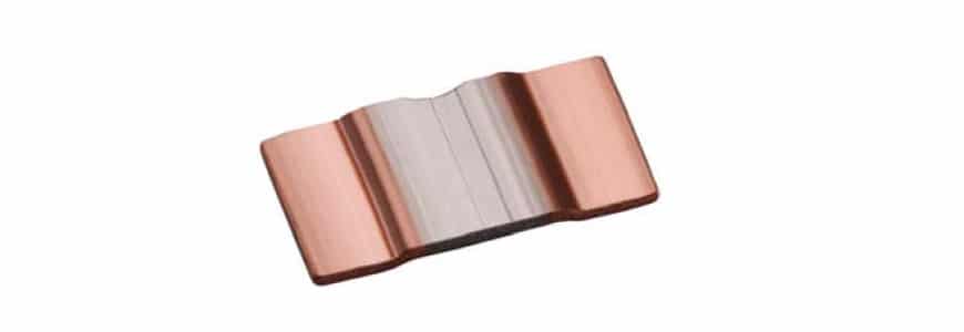
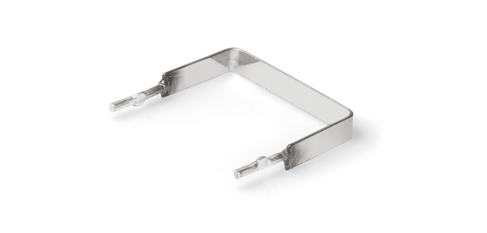
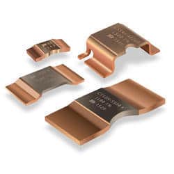
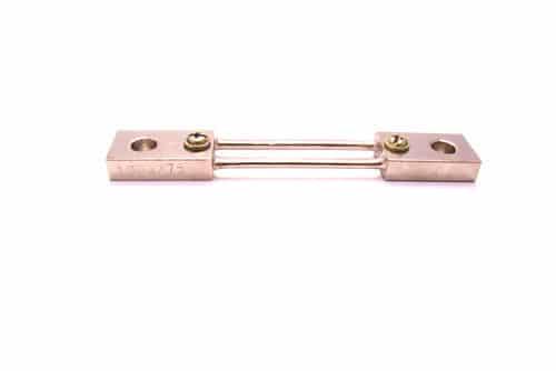
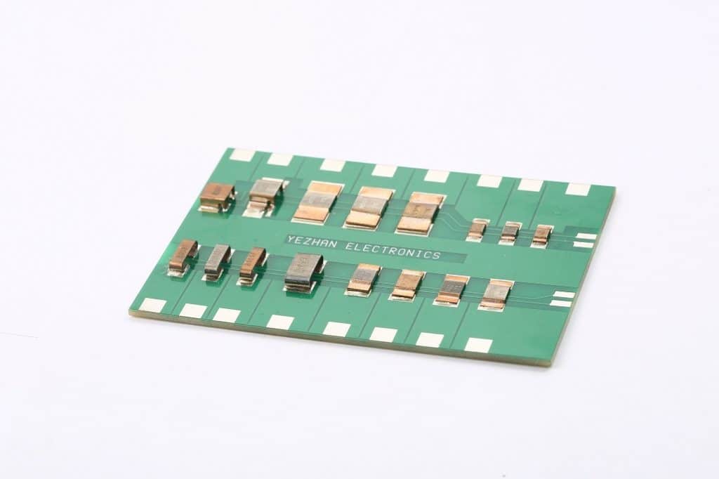
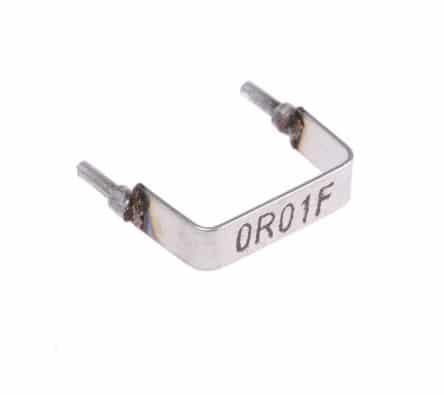
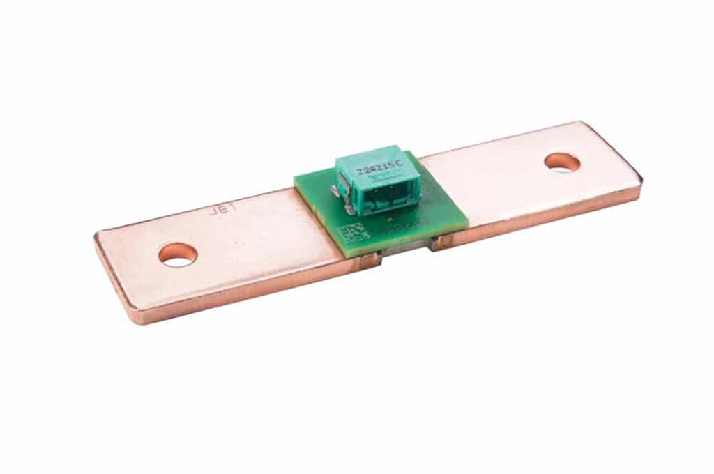
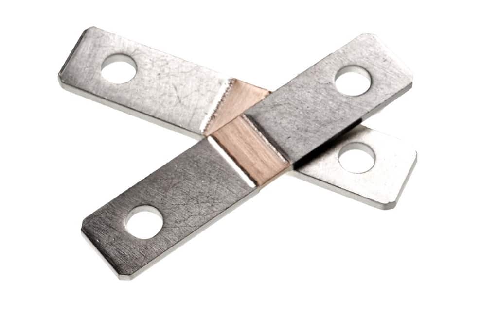
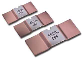
A shunt resistor is a resistor with very low resistance. Sometimes it is a metal piece. Sometimes it is a PCB trace, sometimes it is a normal resistor. Whatever it is, the resistance of a shunt resistor is too low so that the power loss across the resistor becomes very low. As high current flows through these resistances, this resistance should have a good heat-dissipating system.

These shunt resistors can be connected in any configuration in the circuit. Based on the position of the shunt resistor we can design our sensing circuit.
Low side shunt resistor based sensing:
Sometimes, the shunt resistor is connected with GND which is shared with the measuring circuit. That means both have a common GND. This type of use is called low-side shunt resistor-based sensing. In this case, we can simply use an amplifier to amplify the voltage across the resistor. Then we can easily calculate the current flowing through this shunt resistor. So, it is one technique of DC Current measurement using Shunt.

Here, the source and the shunt resistor both are connected in common GND with the measuring circuit. This is called the low-side shunt resistor-based sensing.
Here, we can simply use an Op-Amp-based amplifier. Here we used LM358 based non-inverting amplifier.
Calculations for low side shunt resistor based current sensing circuit:
In this circuit, we used DC lamps whose internal resistance is 24 Ohms. And the current rating is 0.5A. A little less current is obtained due to the shunt resistor’s resistance.
I = 12V / (24 Ohm + 0.1 Ohm)
So, I = 0.496 A
On the other hand, the gain of our Amplifier is,
Gain = (R4/R3) + 1; So the gain = (10K/1K) + 1 = 11.
As you see, we are getting an output of 0.56V. So from this let’s find out the current rating through our shunt resistor.
Gain = Op-Amp output voltage/Voltage across the shunt resistor;
So, Voltage across the shunt resistor = Op-Amp output voltage/Gain;
Vshunt = 0.56/11 = 0.051V
So the current through the shunt resistor is,
Ishunt = Vshunt/Rshunt;
Ishunt = 0.051/0.1 = 0.51A
Which is pretty near to our input current. So the final equation for our current sensing circuit will be,
I = Op-Amp output voltage/(Gain x shunt resistance)


According to our equation, here for two lamps loaded circuits, the current is:
I = 1.09/(11*0.1) = 0.991A
And for the three lamps loaded circuit, the current is:
I = 1.62/(11*0.1)=1.473A
Which is an almost accurate result. Using this circuit diagram we can measure the current when the shunt resistor is connected to the low side. But what will happen if the shunt resistor is connected to the high side and the source is floating?
You may find this helpful: How to make a digital DC Ammeter with PIC16F73 micro-controller and Seven Segment display
High side/floating shunt resistor based current sensing circuit
When the shunt resistor is not connected with the measuring circuit in either way of VCC and GND then we can say that the shunt resistor is floating or a High side shunt resistor. In this case, we can use a differential amplifier to measure the voltage across that shunt resistor. Then using some equations, we can calculate the current through the shunt resistor. This is another way of DC Current measurement using Shunt.

As you can see here the shunt resistor R1 is floating. So we used a differential amplifier to measure the voltage across that shunt resistor.
Calculations for high side/floating shunt resistor based current sensing circuit:
The output voltage of a differential amplifier is calculated by this equation,
Vout = Vdif x (R4/R3);
Here Vdif = V2 – V1. Or simply voltage across our shunt resistor. Simply keep in mind that, V2 > V1 and V2 go to the non-inverting terminal of the Op-Amp. There is a detailed calculation for the differential op-amp. But if you just remember this for work, it’s enough.
As you see in our circuit, the current through the load is 0.49A. Now, we’ll see how can we get this result from our calculation.
If this current is multiplied by our shunt resistor, we’ll get the voltage across the shunt resistor.
Vshunt = 0.49×0.1 = 0.049V
Now, gain of our amplifier is,
Gain = R4/R3 = 220K/10K = 22.
Here, from the differential amplifier calculation, we get this equation:
Vout = Vdiff x Gain.
So, Vdiff = Vout/Gain;
Here in our test circuit, we are getting 1.11V at op-amp output. So,
Vdiff = 1.11/22 = 0.0505V
We know, our shut resistor is 0.1 Ohms. So from the V=IR equation,
Ishunt = Vshunt/Rshunt. Here, Vshunt is our Vdiff and Rshunt = 0.1 Ohms
So, Ishunt = 0.0505/0.1 = 0.505A; Which is almost 0.49566A
That means, we can easily find our current through load measuring the output voltage of Op-Amp using this equation:
I = Op-Amp Output/(Gain x Rshunt)
As you can see from this video, we can calculate the load current keeping the source floating. And the test result is completely accurate according to our calculation.


Summarizing:
After learning about two types of circuits we can now summarize that, we can calculate the load current or shunt current using the same equation in two cases.
Load current/ Shunt current = Op-Amp Output voltage/ (Gain of Op-Amp x Shunt resistance)
So all we need to find first is the gain of the used op-amp circuit. Then we can easily measure the load current from Op-Amp output voltage. Now we can use this DC Current measurement using the Shunt technique in many circuits…
I hope this article was helpful to you. I hope, this circuit configuration and other information will help you to make your project. If you need any help, feel free to ask. Thank you. Enjoy!
Liked this article? Subscribe to our newsletter:
or,
Visit LabProjectsBD.com for more inspiring projects and tutorials.
Thank you!
Check this out: 5 coolest multimeters you can buy


2 Comments
Wilson · 31/01/2022 at 8:44 pm
Hello, thanks alot for this, using the high side sensing circuit, what is the maximum current that be sensed from the circuit? Can 100amps DC be sensed with this system?
MKDas · 01/02/2022 at 11:49 am
There is no limitation but first, calculate the loss against the sensing resistor. If you try to sense 100A using a 0.1Ohm resistor then power loss will be 100x100x0.1 = 1000Watt !!! It’s not an efficient way, right? You know the rules, now you can calculate according to your requirement. Then decide which method is suitable for your operation.