When you are working with electronics, especially power electronics you must have to measure line frequency. But in most cases, people do not have a frequency meter. If you knew how to make a frequency meter in a very easy way, you would make one for yourself. Here in this article, we’ll learn how to make Frequency Meter with a PIC16F73 general-purpose microcontroller and LCD display. Using a multi-meter is ok to measure frequency but many people do not have a multimeter with a frequency meter or sometimes, you need to attach a meter onboard not a multi-meter. Considering these issues, making a frequency meter yourself may become very helpful.
⚠️Disclaimer:
Working with electricity involves serious risk. Ensure you have the necessary skills and take proper safety precautions before attempting any electrical projects. Proceed at your own risk — the author assumes no responsibility for any damage, injury, or issues resulting from the use or misuse of the information provided.
All content on this website is original and protected by copyright. Please do not copy or reproduce content without permission. While most of the resources shared here are open-source and freely accessible for your learning and benefit, your respect for our intellectual effort is appreciated.
If you find our tutorials helpful, consider supporting us by purchasing related materials or sharing our work — it helps keep the content flowing.
Need help or have questions? Leave a comment below — the author is always happy to assist!
Table of Contents
What is frequency meter?
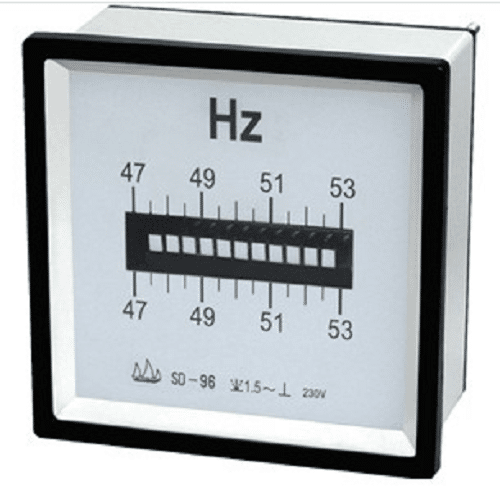
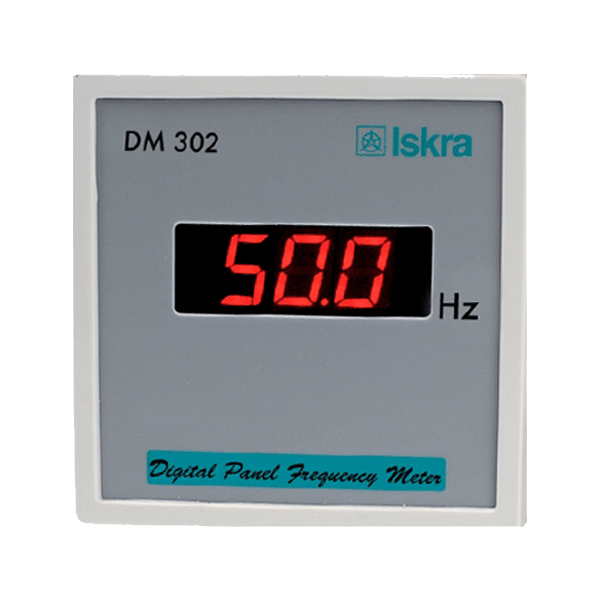
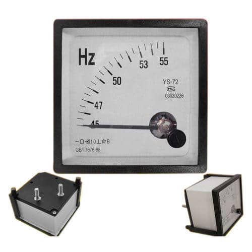
A frequency meter is an instrument that displays the frequency of a periodic electrical signal. There are different types of frequency meters available in the market. Here are 3 types of frequency meters.
Making our own frequency meter:
In the market, there are types of frequency meters. Making our own frequency meter is not so complex at all. All we need to use a micro-controller to sense frequency and display on LCD. Micro-controllers have timers built-in. Using the timer as counter mode, we can easily measure the frequency. Then printing this information on LCD is not a critical job at all. In our circuit, we will use the PIC16F73 microcontroller and 16×2 LCD display.
Circuit diagram:

MikroC Coding
/*******************************************************************************
* Program for, "Frequency Meter"                                               *
* Program Written by_ Engr. Mithun K. Das                                      *
* MCU:PIC16F73; X-Tal: 8Mhz; mikroC pro for PIC v7.6.0                         *
* Date: 15-05-2020                                                             *
*******************************************************************************/

// LCD module connections
sbit LCD_RS at RB2_bit;
sbit LCD_EN at RB3_bit;
sbit LCD_D4 at RB4_bit;
sbit LCD_D5 at RB5_bit;
sbit LCD_D6 at RB6_bit;
sbit LCD_D7 at RB7_bit;

sbit LCD_RS_Direction at TRISB2_bit;
sbit LCD_EN_Direction at TRISB3_bit;
sbit LCD_D4_Direction at TRISB4_bit;
sbit LCD_D5_Direction at TRISB5_bit;
sbit LCD_D6_Direction at TRISB6_bit;
sbit LCD_D7_Direction at TRISB7_bit;
// End LCD module connections


char *freq = "000";
void Display_Freq(unsigned int freq2write)
{
   freq[0] = (freq2write/100) + 48;    // Extract tens digit
   freq[1] = (freq2write/10)%10 + 48;    // Extract tens digit
   freq[2] =  (freq2write/1)%10 + 48;    // Extract ones digit
   Lcd_Out(2, 11, freq);
   Lcd_Out(2,14,"Hz");
}


void main()
{
 TRISA = 0xFF;//all input
 TRISC = 0x00;
 PORTC = 0x00;
 PORTA = 0x00;
 ADCON1=0x00;
 Delay_ms(1000);

 OPTION_REG = 0b00101000; //Timer settings; T0CKI as input
 // of Timer0

 Lcd_Init();
 Lcd_Cmd(_LCD_CLEAR);
 Lcd_Cmd(_LCD_CURSOR_OFF);
 Lcd_Out(1,1,"FREQUENCY METER");
 Lcd_Out(2,1,"WITH PIC16F73  ");
 Delay_ms(2000);
 Lcd_Cmd(_LCD_CLEAR);

  while(1)
  {

      TMR0=0;
      Delay_ms(985);  // Delay 1 Sec // you need to calibrate this delay for accurate result
      Lcd_Out(2,1,"FREQUENCY:");
      Display_Freq(TMR0);


  }// while
}// void main
Here we used Timer0 as counter mode.
Timer0 settings:

Timer0 has a physical input clock pin (RA4/T0CKI). Using this input we can measure the pulse number for a certain time.
Note that, as the timer is 8bit. So we can only measure up to 256Hz with this method. If you need to measure a higher frequency, then we have to use the INT0 hardware interrupt.
Test result:
Conclusion:
We have learned to make a frequency meter using the Timer counter mode of the micro-controller. This frequency meter can be used in panel meters or similar sectors. As this meter can measure upto 256Hz so we can call it a low-frequency meter. Making a higher frequency meter is not complex at all. I hope I’ll cover that in another article.
Liked this article? Subscribe to our newsletter:
or,
Visit LabProjectsBD.com for more inspiring projects and tutorials.
Thank you!
Check this out: 5 coolest multimeters you can buy


0 Comments