This is a small article with a basic feature of LM555 or NE555 timer IC. This timer IC is very common and can be used in different circuits in different operating configurations. In this article, we are going to generate a PWM signal using NE555 timer IC.
⚠️Disclaimer:
Working with electricity involves serious risk. Ensure you have the necessary skills and take proper safety precautions before attempting any electrical projects. Proceed at your own risk — the author assumes no responsibility for any damage, injury, or issues resulting from the use or misuse of the information provided.
All content on this website is original and protected by copyright. Please do not copy or reproduce content without permission. While most of the resources shared here are open-source and freely accessible for your learning and benefit, your respect for our intellectual effort is appreciated.
If you find our tutorials helpful, consider supporting us by purchasing related materials or sharing our work — it helps keep the content flowing.
Need help or have questions? Leave a comment below — the author is always happy to assist!
What is PWM (Pulse Width Modulation)?
PWM or Pulse Width Modulation is a kind of digital signal where the frequency is kept in a fixed range and the duration of the on-time and off-time is varied. This digital signal is mostly used in DC loads to deliver variable power or controlled power.

The frequency of the signal is 1/T where T = total time.
Where, Total time = on time + off time.
Depending on this on time and off time, the duty can be calculated.
duty = on time/ total time X 100 %

PWM signal generation using NE555 Timer IC:
We can use NE555 timer IC to generate PWM with this circuit diagram:
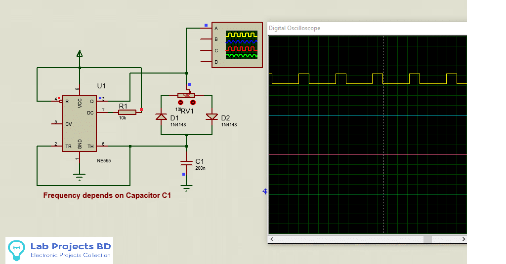
Here the timer IC is operating in free-running mode. A pot and two signal diodes are used to make feedback to the threshold pin. A timing capacitor C1 is used and the output frequency is depending on this capacitor. The RV1 variable resistor is used to control the on-time and off-time that means the duty cycle of the PWM signal.
You may find this article helpful: Make simple AC dimmer using NE555
Simulation Result:
This article is small but the use of this circuit is not so small. This circuit can be used in different systems where a high-frequency PWM signal is required and EMI is involved. So I’ll request to take it seriously. Before applying this circuit to any field test the signals using an oscilloscope rather than testing only using a multimeter. Low price oscilloscopes are available in the market now-a-days. Because there may be distortions in the signal due to bad capacitors. So before applying this circuit, the signal must be checked.
I hope this project was helpful to you. If you make one for yourself, it will be a great pleasure for me. Anywhere you need help, let me know. Please share this project and subscribe to my blog. Thank you.
Liked this article? Subscribe to our newsletter:
or,
Visit LabProjectsBD.com for more inspiring projects and tutorials.
Thank you!
Check this out: 5 coolest multimeters you can buy


3 Comments
Eze · 08/04/2021 at 9:08 am
Please complete this circuit to become pwm inverter circuit
MKDas · 08/04/2021 at 9:47 am
maybe later
sohel · 02/06/2022 at 11:08 am
I wanna to start a new journey with electronics.