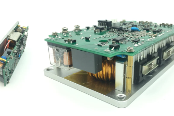
One of the very useful transformerless power supplies using Viper12A IC can be used in many applications. It is sufficient to run micro-controllers, sensors, displays, relays, and so on. With very few numbers of components, we can get a reliable transformerless power supply with Viper12A.
⚠️Disclaimer:
Working with electricity involves serious risk. Ensure you have the necessary skills and take proper safety precautions before attempting any electrical projects. Proceed at your own risk — the author assumes no responsibility for any damage, injury, or issues resulting from the use or misuse of the information provided.
All content on this website is original and protected by copyright. Please do not copy or reproduce content without permission. While most of the resources shared here are open-source and freely accessible for your learning and benefit, your respect for our intellectual effort is appreciated.
If you find our tutorials helpful, consider supporting us by purchasing related materials or sharing our work — it helps keep the content flowing.
Need help or have questions? Leave a comment below — the author is always happy to assist!
***Warning: An electrocution hazard exists during experimentation with transformerless circuits that interface to wall power. There is no transformer for power-line isolation in the following circuits, so the user must be very careful and assess the risks from line transients in the user’s application. An isolation transformer should be used when probing the following circuits.
Table of Contents
About Viper12A:
This is actually a PWM controller with high voltage power MOSFET inside. Usually used in low power standby power supplies, battery chargers, auxiliary power supply, etc.

You can check this article too: Transformerless power supply design guide in detail with calculator
Circuit diagram using Viper12A:

Circuit explanation of power supply with Viper12A:
Here, R1 is used to limit the inrush current and L1 and C1&2 are used to rectify the AC with a filter to get DC voltage. The L2 is the main inductor in this circuit. In this circuit, the inductor should not be used less than 1mH. Diode D2 is supplying the power to VDD and D3 & D4 are generating the feedback voltage. If you need another voltage rather than 12, change the value of this Zener diode D4. C5 and C6 are used to filter the noise from the feedback signal. And finally, C4 is used as the main filter capacitor for the low voltage side. A safety Zener diode D6 of 15V (higher than the output voltage) is used to limit the initial voltage spike during startup. And D5 is the freewheeling diode. Must be used any Ultra Fast diode.
Conclusion:
This article was a serial port of the previous post (Transformerless power supply design guide). As this circuit performs much better than the capacitor or resistor-based power supplies and I’ve been using this circuit in many applications and field running (24/7) devices for a long time so I decided to share the diagram. If you can design the PCB carefully keeping sufficient PCB space as a heatsink, this circuit will last a long time. The average power delivery is 100mA. And most interesting this is this circuit works from 15V to 300V wide (maybe extra-wide) range.
I hope this project was helpful to you. If you make one for yourself, it will be a great pleasure for me. Anywhere you need help, let me know. Please share this project and subscribe to my blog. Thank you.
Liked this article? Subscribe to our newsletter:
or,
Visit LabProjectsBD.com for more inspiring projects and tutorials.
Thank you!
Check this out: 5 coolest multimeters you can buy


5 Comments
Joy · 12/02/2021 at 11:51 am
Thank you… Nice Project..
Paulo · 27/06/2022 at 5:16 am
Olá Mithun, Paulo do Brazil.
Não entendi como o CI Viper12A, dá a partida, pois sua alimentação é posterior, após o funcionamento.
Obrigado, parabéns pela publicação.
Hello Mithun, Paulo from Brazil.
I don’t understand how the CI Viper12A starts, because its power is later, after the operation.
Thank you, congratulations on the publication.
MKDas · 27/06/2022 at 3:23 pm
It has an internal regulator to start.
Joao Bragag · 18/04/2025 at 12:10 am
BOA TARDE – CIRCUITO COM VIPPER-12A NO PINO DO GATE DO IRGP4066D QUE TRABALHA COM 160 VDC (CAPACITOR ELETROLÍTICO) NO COLLETOR PARA IMPULCIONAR MOTOR INDUÇÃO VDC ESTEIRA DE GINASTICA – AUMENTANDO RPM DO MOTOR O CI VIPPER-12A AUMENTA A VDC NO GATE E QUANDO CHEGA A 5 VDC DESLIGA MOTOR – DEVO AUMENTAR VDC NO COLLETOR DO IGBT OU TROCAR CAPACITOR ELETROLÍTICO 470uF -400VDC PARA AMIOR CAPACIDADE? – MUITO OBRIGADO PELO APOIO DE TODOS.
GOOD AFTERNOON – CIRCUIT WITH VIPPER-12A ON THE GATE PIN OF THE IRGP4066D THAT WORKS WITH 160 VDC (ELECTROLYTIC CAPACITOR) ON THE COLLECTOR TO BOOST THE VDC INDUCTION MOTOR ON THE ELETRIC TREADMILL – INCREASING THE MOTOR RPM, THE VIPPER-12A IC INCREASES THE VDC ON THE GATE AND WHEN IT REACHES 5 VDC, IT TURNS OFF THE MOTOR – SHOULD I INCREASE VDC ON THE IGBT COLLECTOR OR CHANGE THE 470uF -400VDC ELECTROLYTIC CAPACITOR FOR GREATER CAPACITY? – THANK YOU VERY MUCH FOR EVERYONE’S SUPPORT.
MKDas · 21/04/2025 at 9:27 pm
Kindly explain me in WhatsApp