In this article, we are learning about PWM Generation with STM32. Here we are using STM32F103C8Tx MCU, but you can also follow the same way for most of the other MCUs. So let’s start!
⚠️Disclaimer:
Working with electricity involves serious risk. Ensure you have the necessary skills and take proper safety precautions before attempting any electrical projects. Proceed at your own risk — the author assumes no responsibility for any damage, injury, or issues resulting from the use or misuse of the information provided.
All content on this website is original and protected by copyright. Please do not copy or reproduce content without permission. While most of the resources shared here are open-source and freely accessible for your learning and benefit, your respect for our intellectual effort is appreciated.
If you find our tutorials helpful, consider supporting us by purchasing related materials or sharing our work — it helps keep the content flowing.
Need help or have questions? Leave a comment below — the author is always happy to assist!
Table of Contents
What is a PWM signal:
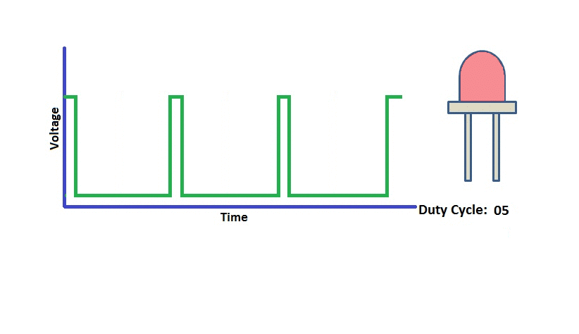
PWM or Pulse Width Modulation is a kind of digital signal where the on-time and off-time can be varied when required.
the PWM signal can be explained by the following image:

so, the duty time = on-time/(on-time + off-time).
and more on time, more the output voltage(avg), or more brightness in a simple way like this animation.
Application of PWM signal:
When you need to control a load or a voltage with a microcontroller, in most cases, you can use a PWM signal as the controlling signal. For example, you need to drive a DC motor at different speeds with a microcontroller. Then you can use a PWM signal which you can generate with your microcontroller and use this PWM signal to drive a MOSFET which is driving the Motor.

Now, let’s generate our PWM signal with STM32 MCU.
PWM Generation with STM32:
After opening a new project or from your existing project, go to timers from the Timers settings.

Then check which timer is having PWM and also the pin you can use for your MCU. In my case, I use TM2 as an example. Then select the channel you need to set for PWM.
Then from ‘Parameters Settings’, set Prescaler and Counter period. Prescaler sets the frequency parameters which are related to the MCU frequency you selected on the clock setting page. And the counter period is like the % settings. In my case, I kept both of Prescaler and the counter period to 255. Which means, 0 = 0% and 255 = 100% of the duty cycle.
Now, save the project to generate the code.
Code:
In main.c file, simply add the following lines:
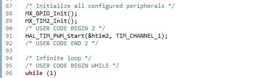
This will start the PWM signal and in this case, the handler is Timer2(htim2) then simply call the compare to set the PWM duty cycle where you need.

Now, build the project and check the output.
Output:

You can check varying the value of x in “__HAL_TIM_SET_COMPARE(&htim2,TIM_CHANNEL_1, x);” line.
End:
I hope, this article will help you learn STM32. See you soon with something helpful. Thanks.
You can check my other articles too:
- Reading ADC with DMA in STM32 MCU
- ADC Reading with STM32103C8Tx (BluePill)
- Adafruit_FONA Library with ESP32
- INA219 interfacing with STM32
- Logging Data to Excel from Arduino
- STM32 as USB Device
Liked this article? Subscribe to our newsletter:
or,
Visit LabProjectsBD.com for more inspiring projects and tutorials.
Thank you!


0 Comments