Learn how to interface the DS3231 RTC chip with STM32 using the I2C communication protocol. This article provides a complete example code for interfacing DS3231 with STM32 that can be used as a reference for your projects.
⚠️Disclaimer:
Working with electricity involves serious risk. Ensure you have the necessary skills and take proper safety precautions before attempting any electrical projects. Proceed at your own risk — the author assumes no responsibility for any damage, injury, or issues resulting from the use or misuse of the information provided.
All content on this website is original and protected by copyright. Please do not copy or reproduce content without permission. While most of the resources shared here are open-source and freely accessible for your learning and benefit, your respect for our intellectual effort is appreciated.
If you find our tutorials helpful, consider supporting us by purchasing related materials or sharing our work — it helps keep the content flowing.
Need help or have questions? Leave a comment below — the author is always happy to assist!
Table of Contents
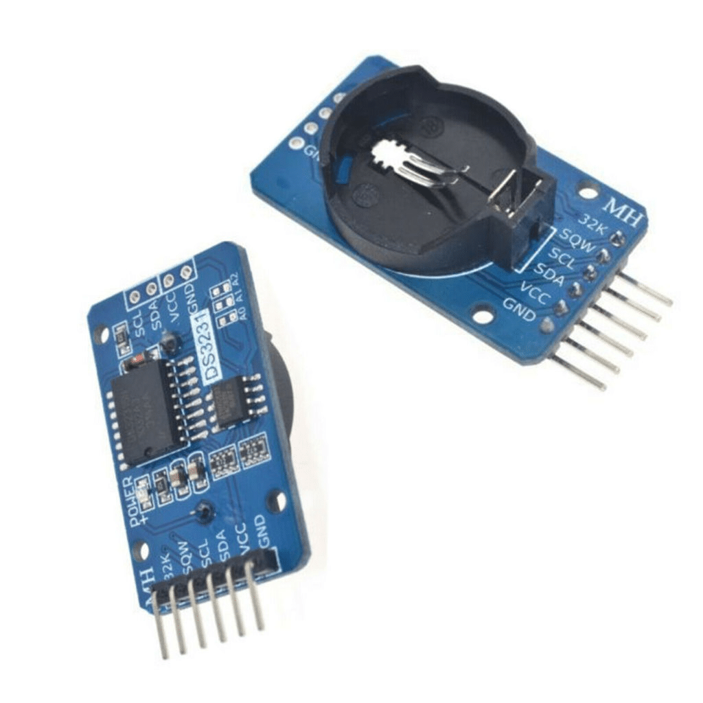
About DS3231:
DS3231 is a popular RTC (Real-Time Clock) chip that provides high-accuracy time and date information. The DS3231 is widely used in various applications, including data loggers, time-keeping systems, and alarm clocks. In this article, we will discuss how to interface the DS3231 RTC chip with the STM32 microcontroller using the I2C communication protocol and provide an example code.
To interface ds3231, we need to connect the SCL and SDA pins with pull-up resistors (4K7~10K). You can follow the followings:
Hardware Required:
- DS3231 RTC chip
- STM32 microcontroller (we will use STM32F103C8T6 in this example)
- Breadboard
- Jumper wires
- 10K pull-up resistors (2), etc
Circuit diagram:
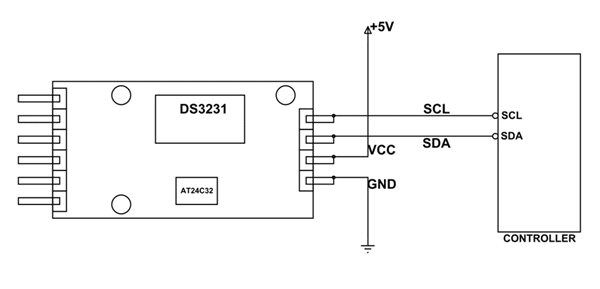
The circuit diagram shows how to connect the DS3231 RTC chip with the STM32 microcontroller. The DS3231 chip’s SDA and SCL pins are connected to the STM32’s PA9 and PA10 pins, respectively. The two 10K pull-up resistors are needed between the SDA and SCL pins and the +3.3V power supply.
Software Required:
Steps to Interface DS3231 with STM32:
- Create a new STM32CubeIDE project.
- Open STM32CubeMX and select the STM32 microcontroller you are using.
- Enable the I2C communication peripheral in the “Pinout & Configuration” tab.
- Configure the I2C communication peripheral with the following settings:
- I2C Mode: I2C Standard
- Clock Speed: 100 KHz
- I2C GPIO pins: PA9 (SDA) and PA10 (SCL)
- Pull-up resistors: Enabled
- Generate the code and open it in STM32CubeIDE.
- In the main.c file, include the following header files:c
#include "stm32f1xx_hal.h"
#include "stdio.h"
7. In the main.c file, add the following global variables:
I2C_HandleTypeDef hi2c1;
8. In the main.c file, add the following function to initialize the I2C communication peripheral:
void MX_I2C1_Init(void)
{
  hi2c1.Instance = I2C1;
  hi2c1.Init.ClockSpeed = 100000;
  hi2c1.Init.DutyCycle = I2C_DUTYCYCLE_2;
  hi2c1.Init.OwnAddress1 = 0;
  hi2c1.Init.AddressingMode = I2C_ADDRESSINGMODE_7BIT;
  hi2c1.Init.DualAddressMode = I2C_DUALADDRESS_DISABLE;
  hi2c1.Init.OwnAddress2 = 0;
  hi2c1 .Init.GeneralCallMode = I2C_GENERALCALL_DISABLE;
 hi2c1.Init.NoStretchMode = I2C_NOSTRETCH_DISABLE;
 if (HAL_I2C_Init(&hi2c1) != HAL_OK)
 {
   Error_Handler();
 }

}
9. In the main.c file, add the following function to read the date and time from the DS3231 RTC chip:
void readDS3231(uint8_t *data, uint8_t len)
{
  HAL_I2C_Mem_Read(&hi2c1, 0x68, 0x00, I2C_MEMADD_SIZE_1BYTE, data, len, HAL_MAX_DELAY);
}
This function reads the data from the DS3231 RTC chip using the I2C communication protocol. The DS3231 chip’s I2C address is 0x68, and the date and time data are stored in registers 0x00 to 0x06. 10. In the main function, call the MX_I2C1_Init() function to initialize the I2C communication peripheral.
- In the main function, call the
readDS3231()function to read the date and time data from the DS3231 RTC chip. - In the main function, print the date and time data to the console using the
printf()function.
Example Code:
Here is the complete example code to interface the DS3231 RTC chip with STM32 using the I2C communication protocol.
#include "stm32f1xx_hal.h"
#include "stdio.h"

I2C_HandleTypeDef hi2c1;

void SystemClock_Config(void);
static void MX_GPIO_Init(void);
static void MX_I2C1_Init(void);

void Error_Handler(void)
{
}

void readDS3231(uint8_t *data, uint8_t len)
{
	HAL_I2C_Mem_Read(&hi2c1, 0x68, 0x00, I2C_MEMADD_SIZE_1BYTE, data, len,
			HAL_MAX_DELAY);
}

int main(void)
{
	HAL_Init();
	SystemClock_Config();
	MX_GPIO_Init();
	MX_I2C1_Init();

	uint8_t data[7];
	readDS3231(data, 7);

	printf("Date: %02x/%02x/20%02x\n", data[4], data[5], data[6]);
	printf("Time: %02x:%02x:%02x\n", data[2], data[1], data[0]);

	while (1)
	{
	}
}

void SystemClock_Config(void)
{
	RCC_OscInitTypeDef RCC_OscInitStruct;
	RCC_ClkInitTypeDef RCC_ClkInitStruct;

	__HAL_RCC_PWR_CLK_ENABLE();
	__HAL_PWR_VOLTAGESCALING_CONFIG(PWR_REGULATOR_VOLTAGE_SCALE1);

	RCC_OscInitStruct.OscillatorType = RCC_OSCILLATORTYPE_HSI;
	RCC_OscInitStruct.HSIState = RCC_HSI_ON;
	RCC_OscInitStruct.HSICalibrationValue = RCC_HSICALIBRATION_DEFAULT;
	RCC_OscInitStruct.PLL.PLLState = RCC_PLL_NONE;
	if (HAL_RCC_OscConfig(&RCC_OscInitStruct) != HAL_OK)
	{
		Error_Handler();
	}

	RCC_ClkInitStruct.ClockType = RCC_CLOCKTYPE_HCLK | RCC_CLOCKTYPE_SYSCLK
			| RCC_CLOCKTYPE_PCLK1 | RCC_CLOCKTYPE_PCLK2;
	RCC_ClkInitStruct.SYSCLKSource = RCC_SYSCLKSOURCE_HSI;
	RCC_ClkInitStruct.AHBCLKDivider = RCC_SYSCLK_DIV1;
	RCC_ClkInitStruct.APB1CLKDivider = RCC_HCLK_DIV1;
	RCC_ClkInitStruct.APB2CLKDivider = RCC_HCLK_DIV1;
	if (HAL_RCC_ClockConfig(&RCC_ClkInitStruct, FLASH_LATENCY_0) != HAL_OK)
	{
		Error_Handler();
	}
}

static void MX_I2C1_Init(void)
{
	hi2c1.Instance = I2C1;
	hi2c1.Init.ClockSpeed = 100000;
	hi2c1.Init.DutyCycle = I2C_DUTYCYCLE_2;
	hi2c1.Init.OwnAddress1 = 0;
	hi2c1.Init.AddressingMode = I2C_ADDRESSINGMODE_7BIT;
	hi2c1.Init.DualAddressMode = I2C_DUALADDRESS_DISABLE;
	hi2c1.Init.OwnAddress2 = 0;
	hi2c1.Init.GeneralCallMode = I2C_GENERALCALL_DISABLE;
	hi2c1.Init.NoStretchMode = I2C_NOSTRETCH_DISABLE;
	if (HAL_I2C_Init(&hi2c1) != HAL_OK)
	{
		Error_Handler();
	}
}

static void MX_GPIO_Init(void)
{
	__HAL_RCC_GPIOC_CLK_ENABLE();
}

void HAL_MspInit(void)
{
	__HAL_RCC_AFIO_CLK_ENABLE();
}

void HAL_I2C_MspInit(I2C_HandleTypeDef *i2cHandle)
{
	GPIO_InitTypeDef GPIO_InitStruct =
	{ 0 };
	if (i2cHandle->Instance == I2C1)
	{
		__HAL_RCC_I2C1_CLK_ENABLE();
		__HAL_RCC_GPIOB_CLK_ENABLE();
		/**I2C1 GPIO Configuration
		 PB6     ------> I2C1_SCL
		 PB7     ------> I2C1_SDA
		 */
		GPIO_InitStruct.Pin = GPIO_PIN_6 | GPIO_PIN_7;
		GPIO_InitStruct.Mode = GPIO_MODE_AF_OD;
		GPIO_InitStruct.Speed = GPIO_SPEED_FREQ_HIGH;
		HAL_GPIO_Init(GPIOB, &GPIO_InitStruct);
	}
}

void HAL_I2C_MspDeInit(I2C_HandleTypeDef *i2cHandle)
{
	if (i2cHandle->Instance == I2C1)
	{
		__HAL_RCC_I2C1_CLK_DISABLE();
		HAL_GPIO_DeInit(GPIOB, GPIO_PIN_6 | GPIO_PIN_7);
	}
}

#ifdef USE_FULL_ASSERT
void assert_failed(uint8_t *file, uint32_t line)
{
}
#endif
Conclusion:
In conclusion, interfacing the DS3231 RTC chip with STM32 is a straightforward process. The DS3231 chip communicates with the STM32 using the I2C communication protocol, and the date and time data are stored in registers 0x00 to 0x06. In this article, we have provided a complete example code to interface the DS3231 RTC chip with STM32, which can be used as a reference for your projects.
Read more on:
- INA219 interfacing with STM32
- STM32 as USB Device
- Digital Clock with DS3231 & PIC microcontroller
- Digital Clock with PIC16F676 & Seven Segment Display
- Digital Clock using a PIC microcontroller & RTC DS1307
Liked this article? Subscribe to our newsletter:
or,
Visit LabProjectsBD.com for more inspiring projects and tutorials.
Thank you!


0 Comments