Learn how to interface an ST7567 display with an Arduino using this guide. Get step-by-step instructions and sample code to get started with displaying graphics and icons on your ST7567 display.
⚠️Disclaimer:
Working with electricity involves serious risk. Ensure you have the necessary skills and take proper safety precautions before attempting any electrical projects. Proceed at your own risk — the author assumes no responsibility for any damage, injury, or issues resulting from the use or misuse of the information provided.
All content on this website is original and protected by copyright. Please do not copy or reproduce content without permission. While most of the resources shared here are open-source and freely accessible for your learning and benefit, your respect for our intellectual effort is appreciated.
If you find our tutorials helpful, consider supporting us by purchasing related materials or sharing our work — it helps keep the content flowing.
Need help or have questions? Leave a comment below — the author is always happy to assist!
Table of Contents
About ST7567 Display:
The ST7567 is a popular LCD controller used for small to medium-sized monochrome graphical displays. It is a low-power, high-performance controller that can drive up to 132×64 pixels with a 1-bit or 4-bit grayscale.
The ST7567 controller has embedded RAM that can store up to 8 pages of 132×8 bits each. This RAM can be accessed via an 8-bit parallel interface or a 4-wire serial interface. The controller can display up to 16 grayscale levels per pixel, allowing for detailed images and icons.
Pin diagram of ST7567:
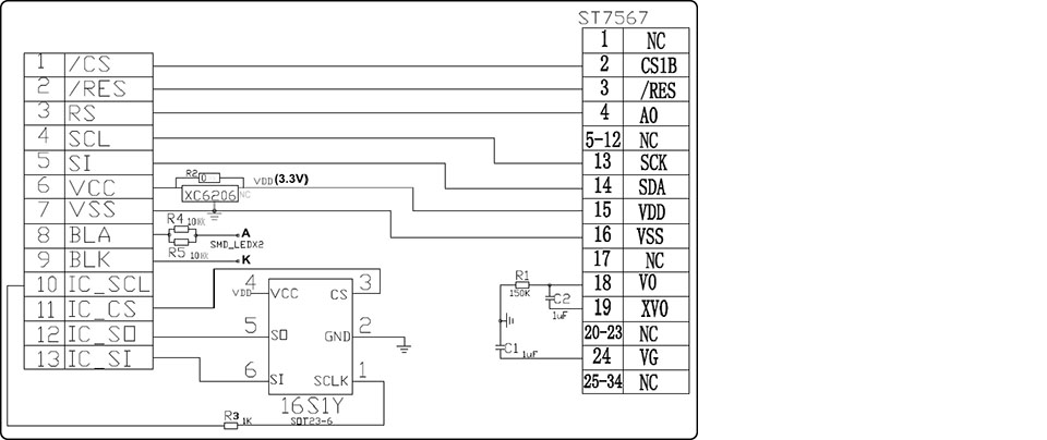
Note that the display itself is 3.3V but the data pins are FT means it works with up to 5.5V. So when you connect with Arduino or any MCU, power it up with 3.3V but use the signal pins directly.
Advantage of ST7567:
One of the main advantages of the ST7567 display is its low power consumption. It uses a voltage multiplier circuit to generate the high voltage needed for LCD driving. This circuit can generate voltages up to 22V from a 3V power supply, making it suitable for battery-powered devices.
The ST7567 also includes several features that make it easy to use in a wide range of applications. It includes a built-in oscillator that generates the necessary timing signals for LCD driving. It also includes a temperature sensor that can be used to compensate for changes in the LCD response to temperature.
Application of ST7567:
The ST7567 display is commonly used in a variety of applications, including consumer electronics, medical devices, and industrial equipment. It is often used in devices that require a low-power, high-resolution display that can operate in a wide range of temperatures.
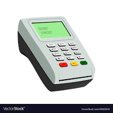
One common application of the ST7567 display is in smartwatches and fitness trackers. These devices require a small, low-power display that can display detailed graphics and icons. The ST7567 is a popular choice for these devices due to its low power consumption and high resolution.
Another common application of the ST7567 display is in medical devices. These devices often require a high-resolution display that can operate in a wide range of temperatures. The ST7567 is a popular choice for these devices due to its low power consumption and high-temperature range.
Interfacing ST7567 with Arduino:
To interface ST7567 you need to download the ST7567_FB.h library and add it to your Arduino IDE.
Now use this example code to test your display:
/*
128x64 ST7567 connections in SPI mode (only 5-6 wires between LCD and MCU):
#01 LED -> D6, GND or any pin via resistor
#02 RST -> D9 or any pin
#03 CS -> D10 or any pin
#04 DC -> D8 or any pin
#05 SCK -> D13/SCK
#06 SDI -> D11/MOSI
#07 3V3 -> VCC (3.3V)
#08 GND -> GND
*/
#define LCD_CS 53
#define LCD_DC 9
#define LCD_RST 10
#include "ST7567_FB.h"
#include <SPI.h>
ST7567_FB lcd(LCD_DC, LCD_RST, LCD_CS);
// from PropFonts library
#include "c64enh_font.h"
void setup()
{
Serial.begin(9600);
lcd.init();
lcd.setRotation(2);
lcd.setContrast(10);
lcd.cls();
lcd.setFont(c64enh);
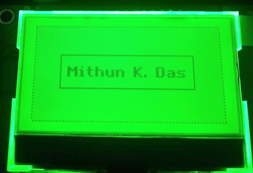
lcd.printStr(ALIGN_CENTER, 28, "Mithun K. Das");
lcd.drawRectD(0,0,128,64,1);
lcd.drawRect(18,20,127-18*2,63-20*2,1);
lcd.display();
}
void loop()
{
}
If your connections are ok, then you should see this:
And you can do something with graphics too.
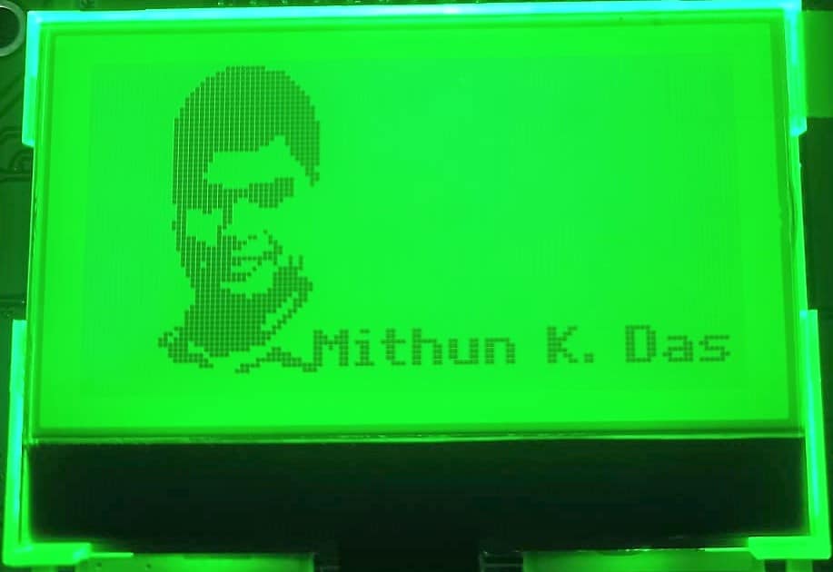
For the above graphics, I used image to cpp converter. You can also use similar converters for your graphics too.
Example code for the graphics:
Here is the code I used for the above graphics:
 /*
 128x64 ST7567 connections in SPI mode (only 5-6 wires between LCD and MCU):

 #01 LED  -> D6, GND or any pin via resistor
 #02 RST  -> D9 or any pin
 #03 CS   -> D10 or any pin
 #04 DC   -> D8 or any pin
 #05 SCK  -> D13/SCK
 #06 SDI  -> D11/MOSI
 #07 3V3  -> VCC (3.3V)
 #08 GND  -> GND
*/

#define LCD_CS 53
#define LCD_DC 9
#define LCD_RST 10

#include "ST7567_FB.h"
#include "fonts_all.h"
#include <SPI.h>
ST7567_FB lcd(LCD_DC, LCD_RST, LCD_CS);


const uint8_t MKD[] PROGMEM = { 64, 12 * 14,
                                0x00, 0x00, 0x00, 0x00, 0x00, 0x00, 0x00, 0x00, 0x00, 0x00, 0x00, 0x00, 0x00, 0x00, 0x00, 0x00,
                                0x00, 0x00, 0x00, 0xc0, 0xe0, 0xf0, 0xf8, 0xfc, 0xfc, 0xfe, 0xfe, 0xff, 0xff, 0xff, 0xff, 0xff,
                                0xff, 0xff, 0xff, 0xfe, 0xfe, 0xfe, 0xfe, 0xfc, 0xf8, 0xf0, 0xe0, 0xc0, 0x00, 0x00, 0x00, 0x00,
                                0x00, 0x00, 0x00, 0x00, 0x00, 0x00, 0x00, 0x00, 0x00, 0x00, 0x00, 0x00, 0x00, 0x00, 0x00, 0x00,
                                0x00, 0x00, 0x00, 0x00, 0x00, 0x00, 0x00, 0x00, 0x00, 0x00, 0x00, 0x00, 0x00, 0x00, 0x00, 0x00,
                                0x00, 0xfc, 0xff, 0xff, 0xff, 0xff, 0xff, 0xff, 0xff, 0xff, 0xff, 0xff, 0xff, 0xff, 0xff, 0xff,
                                0xff, 0xff, 0xff, 0xff, 0x7f, 0x3f, 0x3f, 0xff, 0xff, 0xff, 0xff, 0xff, 0xff, 0xf8, 0x00, 0x00,
                                0x00, 0x00, 0x00, 0x00, 0x00, 0x00, 0x00, 0x00, 0x00, 0x00, 0x00, 0x00, 0x00, 0x00, 0x00, 0x00,
                                0x00, 0x00, 0x00, 0x00, 0x00, 0x00, 0x00, 0x00, 0x00, 0x00, 0x00, 0x00, 0x00, 0x00, 0x00, 0x00,
                                0x00, 0xff, 0xff, 0xff, 0xff, 0xff, 0xff, 0xdf, 0x87, 0x81, 0x81, 0x01, 0x01, 0x01, 0x01, 0x01,
                                0x81, 0x81, 0x80, 0x80, 0x80, 0xc0, 0xc0, 0xc0, 0xc3, 0x07, 0x0f, 0x3f, 0xff, 0x6f, 0x00, 0x00,
                                0x00, 0x00, 0x00, 0x00, 0x00, 0x00, 0x00, 0x00, 0x00, 0x00, 0x00, 0x00, 0x00, 0x00, 0x00, 0x00,
                                0x00, 0x00, 0x00, 0x00, 0x00, 0x00, 0x00, 0x00, 0x00, 0x00, 0x00, 0x00, 0x00, 0x00, 0x00, 0x00,
                                0x00, 0xc7, 0xff, 0xff, 0x0f, 0x0f, 0x0f, 0x1f, 0x1f, 0x0f, 0x8f, 0xff, 0x7f, 0x07, 0x03, 0x03,
                                0x07, 0x07, 0x0f, 0x0f, 0x0f, 0x0f, 0x07, 0x03, 0x03, 0x00, 0x00, 0x00, 0x00, 0x00, 0x00, 0x00,
                                0x00, 0x00, 0x00, 0x00, 0x00, 0x00, 0x00, 0x00, 0x00, 0x00, 0x00, 0x00, 0x00, 0x00, 0x00, 0x00,
                                0x00, 0x00, 0x00, 0x00, 0x00, 0x00, 0x00, 0x00, 0x00, 0x00, 0x00, 0x00, 0x00, 0x00, 0x00, 0x00,
                                0x00, 0x00, 0x0f, 0x7f, 0xfe, 0xfe, 0xfc, 0xbc, 0xf8, 0xf8, 0xff, 0xfe, 0xfe, 0x6e, 0x6c, 0x24,
                                0x22, 0xa2, 0x60, 0x31, 0x36, 0x7c, 0x98, 0x80, 0xe0, 0x80, 0xe0, 0x00, 0x00, 0x00, 0x00, 0x00,
                                0x00, 0x00, 0x00, 0x00, 0x00, 0x00, 0x00, 0x00, 0x00, 0x00, 0x00, 0x00, 0x00, 0x00, 0x00, 0x00,
                                0x00, 0x00, 0x00, 0x00, 0x00, 0x00, 0x00, 0x00, 0x00, 0x00, 0x00, 0x00, 0x00, 0x00, 0x00, 0x00,
                                0x00, 0x00, 0x00, 0x00, 0x81, 0xc7, 0xff, 0xff, 0xff, 0xff, 0xff, 0xfb, 0xfb, 0xf3, 0xf3, 0xf3,
                                0xe1, 0xf0, 0xf0, 0xf0, 0xf8, 0xff, 0x7f, 0x3f, 0x9f, 0xef, 0x7e, 0x3e, 0x0c, 0x00, 0x00, 0x00,
                                0x00, 0x00, 0x00, 0x00, 0x00, 0x00, 0x00, 0x00, 0x00, 0x00, 0x00, 0x00, 0x00, 0x00, 0x00, 0x00,
                                0x00, 0x00, 0x00, 0x00, 0x00, 0x00, 0x00, 0x00, 0x00, 0x00, 0x00, 0x00, 0x00, 0x00, 0x00, 0x30,
                                0x38, 0xe8, 0xf4, 0xfc, 0xff, 0x9f, 0xbf, 0xbf, 0x7f, 0xff, 0xff, 0xff, 0xff, 0x7f, 0x7f, 0x7f,
                                0x7f, 0x3f, 0x3f, 0x3b, 0x98, 0xcc, 0xc6, 0x83, 0x81, 0x00, 0x00, 0x00, 0x00, 0x00, 0x00, 0x00,
                                0x00, 0x00, 0x00, 0x00, 0x00, 0x00, 0x00, 0x00, 0x00, 0x00, 0x00, 0x00, 0x00, 0x00, 0x00, 0x00,
                                0x00, 0x00, 0x00, 0x00, 0x00, 0x00, 0x00, 0x00, 0x00, 0x00, 0x00, 0x00, 0x00, 0x00, 0x00, 0x00,
                                0x00, 0x00, 0x01, 0x01, 0x01, 0x01, 0x01, 0x03, 0x03, 0x02, 0x00, 0x00, 0x00, 0x00, 0x04, 0x06,
                                0x06, 0x02, 0x03, 0x01, 0x01, 0x01, 0x01, 0x03, 0x03, 0x03, 0x03, 0x06, 0x06, 0x04, 0x00, 0x00,
                                0x00, 0x00, 0x00, 0x00, 0x00, 0x00, 0x00, 0x00, 0x00, 0x00, 0x00, 0x00, 0x00, 0x00, 0x00, 0x00 };


void setup() {
  Serial.begin(9600);

  lcd.init();
  lcd.setRotation(2);
  lcd.setContrast(10);
  lcd.cls();

  lcd.drawBitmap(MKD, ALIGN_LEFT, 1);
  lcd.setFont(c64enh);
  lcd.printStr(45, 52, "Mithun K. Das");
  lcd.display();
}

void loop() {
}
Now, you have plenty of example code in that library you added. So? you can make anything to print now.
Conclusion:
In summary, the ST7567 display is a versatile LCD controller that is suitable for a wide range of applications. Its low power consumption, high resolution, and temperature range make it a popular choice for consumer electronics, medical devices, and industrial equipment.
Read more on:
- How to interface an OLED display with an STM32
- How to interface a 7-segment display with STM32
- How to interface the EM18 RFID module with STM32
- Introducing RTOS with stm32
Liked this article? Subscribe to our newsletter:
or,
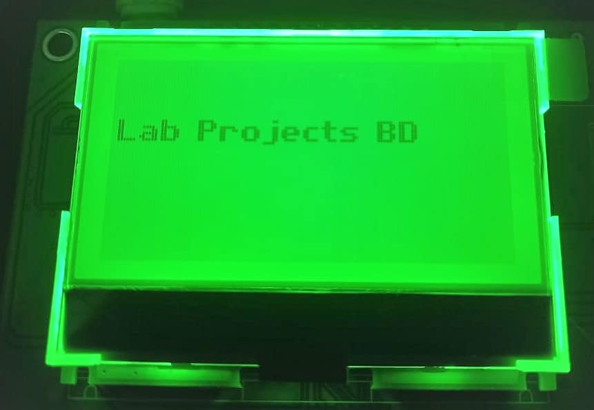
Visit LabProjectsBD.com for more inspiring projects and tutorials.
Thank you!


0 Comments