In renewable energy systems like solar power setups, extracting maximum power from the photovoltaic (PV) panel is crucial for efficiency. This is achieved using a Maximum Power Point Tracking (MPPT) controller, which dynamically adjusts the operating point of the PV panel to harvest the most power. In this article, we’ll explore a Step-by-Step Guide to Building an MPPT Controller with Arduino and a Synchronous Buck Converter.
⚠️Disclaimer:
Working with electricity involves serious risk. Ensure you have the necessary skills and take proper safety precautions before attempting any electrical projects. Proceed at your own risk — the author assumes no responsibility for any damage, injury, or issues resulting from the use or misuse of the information provided.
All content on this website is original and protected by copyright. Please do not copy or reproduce content without permission. While most of the resources shared here are open-source and freely accessible for your learning and benefit, your respect for our intellectual effort is appreciated.
If you find our tutorials helpful, consider supporting us by purchasing related materials or sharing our work — it helps keep the content flowing.
Need help or have questions? Leave a comment below — the author is always happy to assist!
Before we start Building an MPPT Controller with Arduino, the first step is to know the MPPT and synchronous buck converter.
Table of Contents
Understanding MPPT and Synchronous Buck Converter:
MPPT stands for Maximum Power Point Tracking. It’s a technique used in solar power systems (and sometimes wind turbines) to maximize the amount of power extracted from the solar panels under varying conditions.
Here’s how it works:
- Solar Panel Output Varies: A solar panel’s electrical output (both voltage and current) changes depending on factors like sunlight intensity, temperature, and shading.
- Maximum Power Point: For every set of conditions, there’s a specific voltage and current combination at which the solar panel produces maximum power. This is called the Maximum Power Point (MPP).
- MPPT’s Role: An MPPT system is an electronic circuit that constantly tracks the output of the solar panel and adjusts the load to ensure that it’s always operating at or near its MPP. This maximizes the power transfer from the panel to the battery or grid.
Think of it like this: Imagine you’re pedaling a bicycle. You can generate the most power with a certain pedaling speed (cadence). If you pedal too slowly or too quickly, you produce less power. An MPPT is like the gears on your bike, automatically adjusting the resistance to keep you pedaling at the optimal speed for maximum power output.
For solar panels, the MPPT is like this:
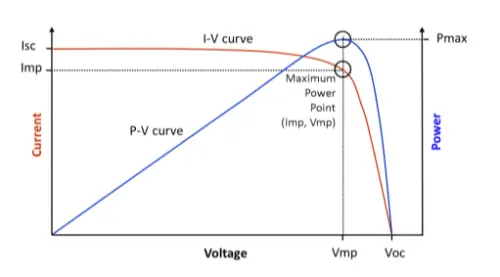
Imagine you have a solar panel with an open-circuit voltage of 22V and a short-circuit current of 10A. If you draw no current from the panel, the voltage remains at 22V, but since the current is zero, the power output is:
Power=Voltage×Current=22V×0A=0W
On the other hand, if you draw the maximum current (10A), the voltage drops to 0V, resulting in:
Power=Voltage×Current=0V×10A=0W
In both extreme cases, the power output is zero.
Now, if you operate the solar panel at 17V, you might get around 8A of current. The power in this case would be:
Power=Voltage×Current=17V×8A=136W
This demonstrates the concept of Maximum Power Point Tracking (MPPT). MPPT ensures that the solar panel operates at the voltage and current combination where it delivers maximum power, which in this example is 136W at 17V.
Use of MPPT:
MPPT is primarily used in solar charge controllers, which regulate the charging of batteries in solar power systems. Here’s why it’s important:
- Increased Energy Harvest: By constantly tracking the MPP, MPPT systems can increase the energy harvested from solar panels by up to 30% compared to traditional controllers that don’t use MPPT.
- Efficiency in Varying Conditions: MPPT is particularly beneficial in situations where sunlight conditions change frequently, such as on cloudy days or when there’s partial shading on the panels.
- Matching Panel and Battery Voltages: MPPT allows for more flexibility in matching the voltage of the solar panels to the voltage of the battery bank, improving system efficiency.
In summary, MPPT is a crucial technology for maximizing the efficiency of solar power systems by ensuring that the solar panels are always operating at their point of maximum power output.
Now, let’s make our own MPPT controller. But before that, I’ll request you to read my other article:
Make an MPPT Solar charge Controller with a Synchronous Buck Converter
What is a synchronous buck converter:
A synchronous buck converter is a type of DC-to-DC converter that steps down a higher input voltage to a lower output voltage efficiently. It’s widely used in modern electronics to power devices like microcontrollers, processors, and other low-voltage components.
***If you want to learn other DC/DC converters, read this article here.
Let’s break it down in simple terms:
- What Does It Do?
- It takes a higher voltage (like 12V or 24V) and converts it to a lower, more usable voltage (like 5V or 3.3V).
- It does this with very little energy wasted, making it ideal for battery-powered and energy-efficient systems.
- Why Is It Called “Synchronous”?
- A regular buck converter uses a diode to control current flow, but a synchronous buck converter replaces the diode with a second transistor (called a MOSFET). This improves efficiency because MOSFETs waste less energy as heat compared to diodes.
- How Does It Work?
- The converter switches the transistors (MOSFETs) on and off rapidly.
- An inductor and capacitor smooth out the output, turning the pulsed voltage into a steady lower voltage.
Let’s take a closer look at how a synchronous buck converter works in a circuit.
In this example, the main control switch (a MOSFET) is placed at the top. This switch connects the input voltage to the output through an inductor for a specific period of time. During this phase, the inductor stores energy and helps regulate the current flow to the load.
When the control switch is turned off, the inductor tries to maintain the current flow. At this point, a diode is typically used to provide a path for the inductor’s current. However, this diode introduces a forward voltage drop, which results in energy loss and reduces the overall efficiency of the converter.
To overcome this limitation, the diode is replaced with a Synchronous Rectifier (SR) MOSFET. The SR MOSFET acts like a switch and has a much lower voltage drop compared to a diode. This significantly reduces power loss and improves the efficiency of the buck converter.
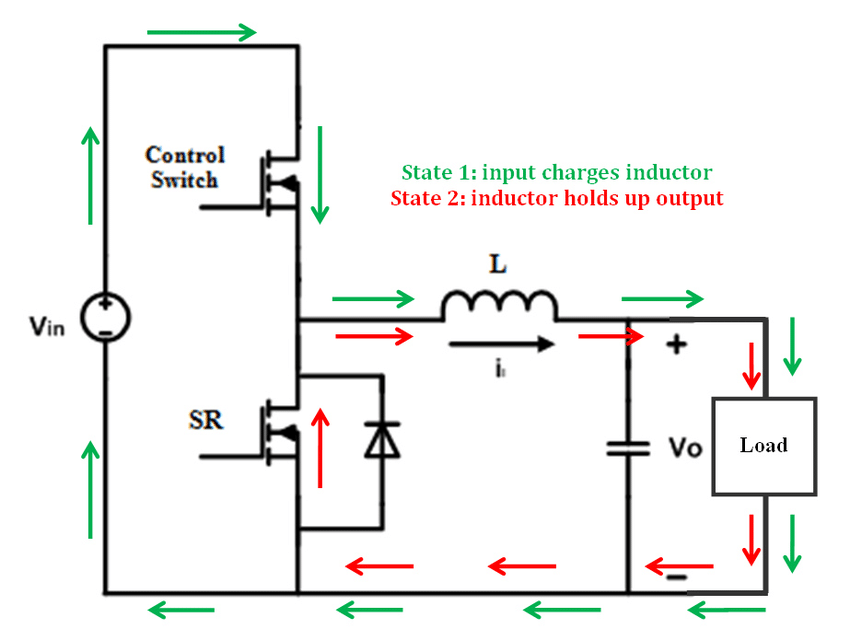
Now, the diode loss is significantly reduced because MOSFETs create a very low-resistance switching path for the inductor’s hold-up current. This improvement directly increases the efficiency of the converter.
The key to making this work is ensuring that the Synchronous Rectifier (SR) MOSFET switches on when the Control Switch (CS) MOSFET is off. However, it’s critical to introduce a dead-time gap between the switching of these two MOSFETs. This prevents both switches from being on simultaneously, which could create a short circuit path for the input source.
And that’s it! This approach ensures high efficiency and safe operation of the synchronous buck converter.
Now, let’s design our own MPPT controller circuit diagram using this concept.
Building an MPPT Controller with Arduino:
Here is the circuit diagram of our MPPT controller using Arduino and a synchronous buck converter
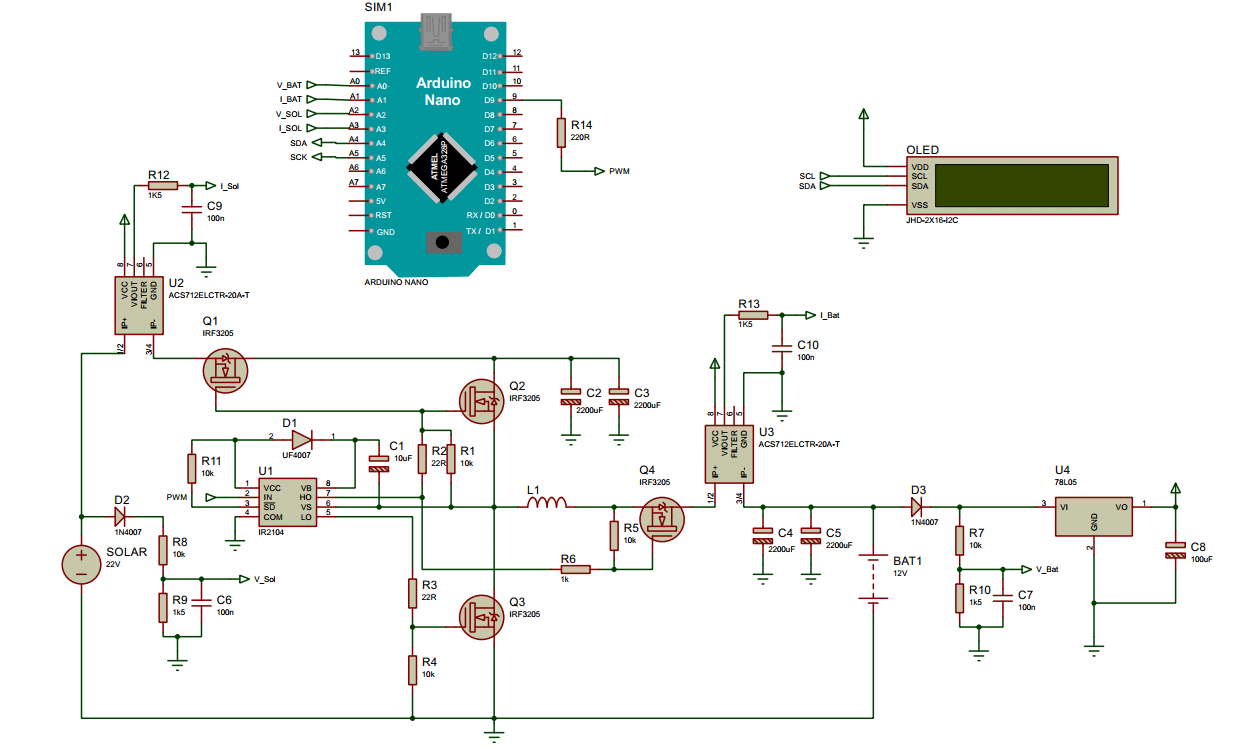
In this circuit, you can see that Q1 and Q4 are additional MOSFETs, but they are configured and switched in a slightly unconventional manner through their gate signaling. These MOSFETs effectively function as diodes while also significantly reducing switching losses. By using MOSFETs instead of traditional diodes, the design takes advantage of their low forward voltage drop.
These additional MOSFETs are synchronized with the Control Switch (main MOSFET) to ensure proper operation and minimize energy loss. This setup is an advanced technique we utilize in our products to enhance both performance and efficiency, making it ideal for modern applications where energy optimization is critical.
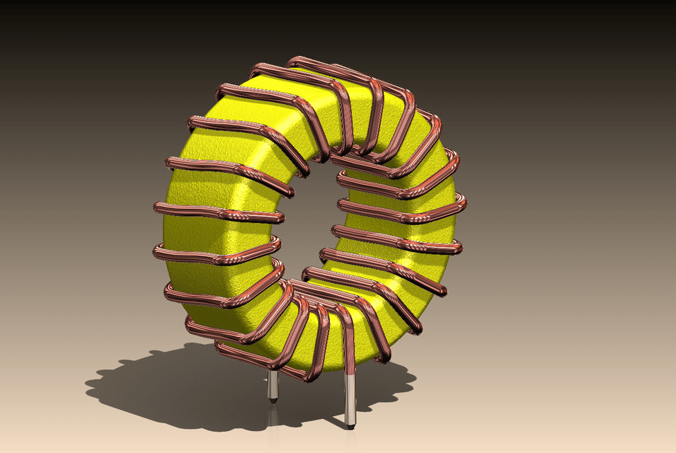
In a typical synchronous buck converter using a gate driver like the IR2104, selecting the right inductor is crucial for achieving maximum efficiency alongside proper circuit configuration.
A higher inductance value simplifies control by reducing the current ripple, but it comes at the cost of increased resistive losses in the inductor due to the longer wire length or thinner wire used in high-inductance coils. Conversely, a lower inductance value minimizes resistive losses, enhancing efficiency, but it increases current ripple, which can make control more challenging and may lead to excessive stress on the components.
Thus, striking the right balance during inductor selection is vital to ensure optimal performance and efficiency. Proper calculations based on output current, switching frequency, ripple requirements, and load conditions are necessary to make the best choice.
Inductor selection guide:
Inductor selection is a critical step in designing a synchronous buck converter because it directly impacts efficiency, ripple current, and transient response. Here’s how to calculate the inductor value:
Key Parameters:
Before selecting the inductor, the following parameters need to be known:
1. Input Voltage (Vin)
2. Output Voltage (Vout)
3. Output Current (Iout)
4. Switching Frequency (f)
5. Inductor Ripple Current (ΔIL), typically 20-40% of the output current.
Formula to Calculate Inductor Value:
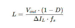
Where:
D=Vout/Vin is the duty cycle of the converter.
Step-by-Step Calculation:
- Define Ripple Current (
ΔIL):
Ripple current is chosen as a fraction of the maximum output current:ΔIL=k⋅Ioutwherekis the ripple current ratio (e.g., k=0.3 for 30%). - Determine the Duty Cycle (
D):D=Vout/Vin. - Calculate Inductance (
L): Using the formula:L=Vout⋅(1−D)ΔIL⋅Fs.
Example Calculation:
Consider the following example:Vin = 12V, Vout = 5V, Iout = 2A, f = 100kHz, and ΔIL = 30% of Iout.
1. Calculate the duty cycle:
D = Vout / Vin = 5 / 12 ≈ 0.4167
2. Calculate the ripple current:
ΔIL = 0.3 × Iout = 0.3 × 2 = 0.6A
3. Calculate the inductance:
L = (Vout × (1 - D)) / (ΔIL × f)
     = (5 × (1 - 0.4167)) / (0.6 × 100,000)
     = (5 × 0.5833) / 60,000
     ≈ 48.6 μH
Thus, a 47 μH or 50 μH inductor would be a good practical choice.
Additional Considerations:
1. Saturation Current: The inductor must have a saturation current rating higher than the peak current in the circuit, which can be calculated as:
Ipeak = Iout + (ΔIL / 2)
2. Core Material: Choose a core material with low losses at the operating frequency.
3. Size and Thermal Considerations: Ensure the inductor can handle the thermal and size constraints of your design.
You can read: All-in-One Electronic tools and Calculators links. This will guide you to design your inductor properly. Check in!
Now, a little bit of experience and practice will make this perfect. Now, let’s see what I made for me here.
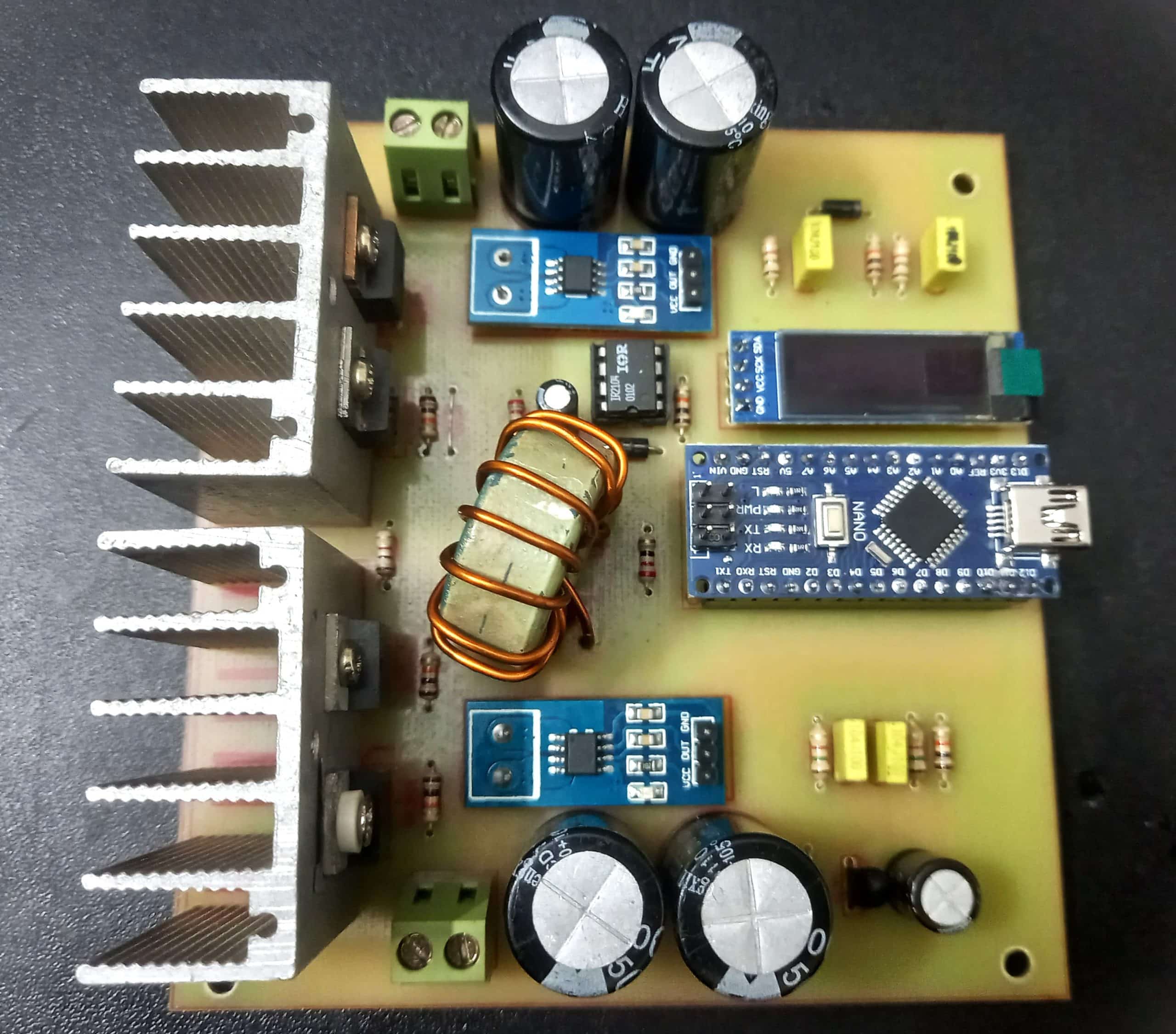
PCB of MPPT controller using Arduino:
Here is what I build.
Now, we need to test our circuit. To begin, we first need to develop the project algorithm and then proceed to write the code. In my project, I am using the Perturb and Observe (P&O) method as the MPPT algorithm. This is one of the most commonly used algorithms for such designs.
Although there are other algorithms available, I prefer the P&O method because of its simplicity and effectiveness in tracking the maximum power point of solar panels.
In this project, I want to structure the algorithm as follows:
- Bulk Charging Mode: When solar power is available, the system will begin charging the battery in Bulk mode. During this phase, the system will deliver the maximum current to the battery until the voltage reaches the predefined bulk maximum limit.
- Float Charging Mode: Once the bulk voltage limit is reached, the system will switch to Float mode. Here, the charging current will gradually decrease, maintaining the battery voltage at a safe level until it reaches the lowest current threshold.
- Rest Mode: After Float mode, the battery will enter a rest phase, where no charging occurs. This allows the battery to stabilize.
- Restart Charging: If the battery voltage drops below the defined rest voltage limit during the rest phase, the system will restart the charging process, beginning again with Bulk mode.
This approach ensures safe and efficient charging of the battery while optimizing its lifespan.
Note: The MPPT algorithm will be used only in bulk mode where the maximum power is necessary. But be noted that, once the battery reaches the bulk voltage limit, it should not exceed that voltage.
I have an article on lead acid battery charging. You can read
- Get a long life of your Lead-Acid battery by selecting the right charging method
- A smart Battery charger circuit design guide
Arduino code for our MPPT controller:
#include <Adafruit_SSD1306.h>
#include "Wire.h"
#define SCREEN_WIDTH 128 // OLED display width, in pixels
#define SCREEN_HEIGHT 32 // OLED display height, in pixels
#define OLED_RESET -1 // Reset pin # (or -1 if sharing Arduino reset pin)
#define SCREEN_ADDRESS 0x3C ///< See datasheet for Address; 0x3D for 128x64, 0x3C for 128x32
Adafruit_SSD1306 display(SCREEN_WIDTH, SCREEN_HEIGHT, &Wire, OLED_RESET);
// Analog input pins
#define SOLAR_VOLTAGE_PIN A2
#define SOLAR_CURRENT_PIN A3
#define BATTERY_VOLTAGE_PIN A0
#define BATTERY_CURRENT_PIN A1
// PWM pin
#define PWM_PIN 3
// Global variables
float solarVoltage = 0.0;
float batteryVoltage = 0.0;
float solarCurrent = 0.0;
float batteryCurrent = 0.0;
// Constants
const int PWM_FREQUENCY = 20000; // 20 kHz
const int pwmMin = 1; // Minimum duty cycle
const int pwmMax = 100; // Maximum duty cycle
const float stepSize = 0.02; // Step size for perturbation
// Global variables
float oldPower = 0; // Previous power reading
float newPower = 0; // Current power reading
int pwmDuty = pwmMin; // Initial PWM duty cycle
int lockoutCnt = 0;
int batteryPercentage = 0;
//control variables
const int BULK = 0, FLOAT = 1, NONE = 2, FULL = 3;
int chargeStage = BULK;
const float minimumBatteryVoltage = 8.0;
const float voltageDifferenceThreshold = 1.0;
const float bulkChargeVoltageThreshold = 14.2;
//Float charging settings
const float LowestBatChargingCurrent = 0.3; //Amp
const float BatUpperLimit = 13.8; //Volt
const float BatLowerLimit = 13.6; //volt
//Full charging settings
unsigned long lastCurrentStableTime = 0;
const unsigned long waitTime = 20 * 60 * 1000;
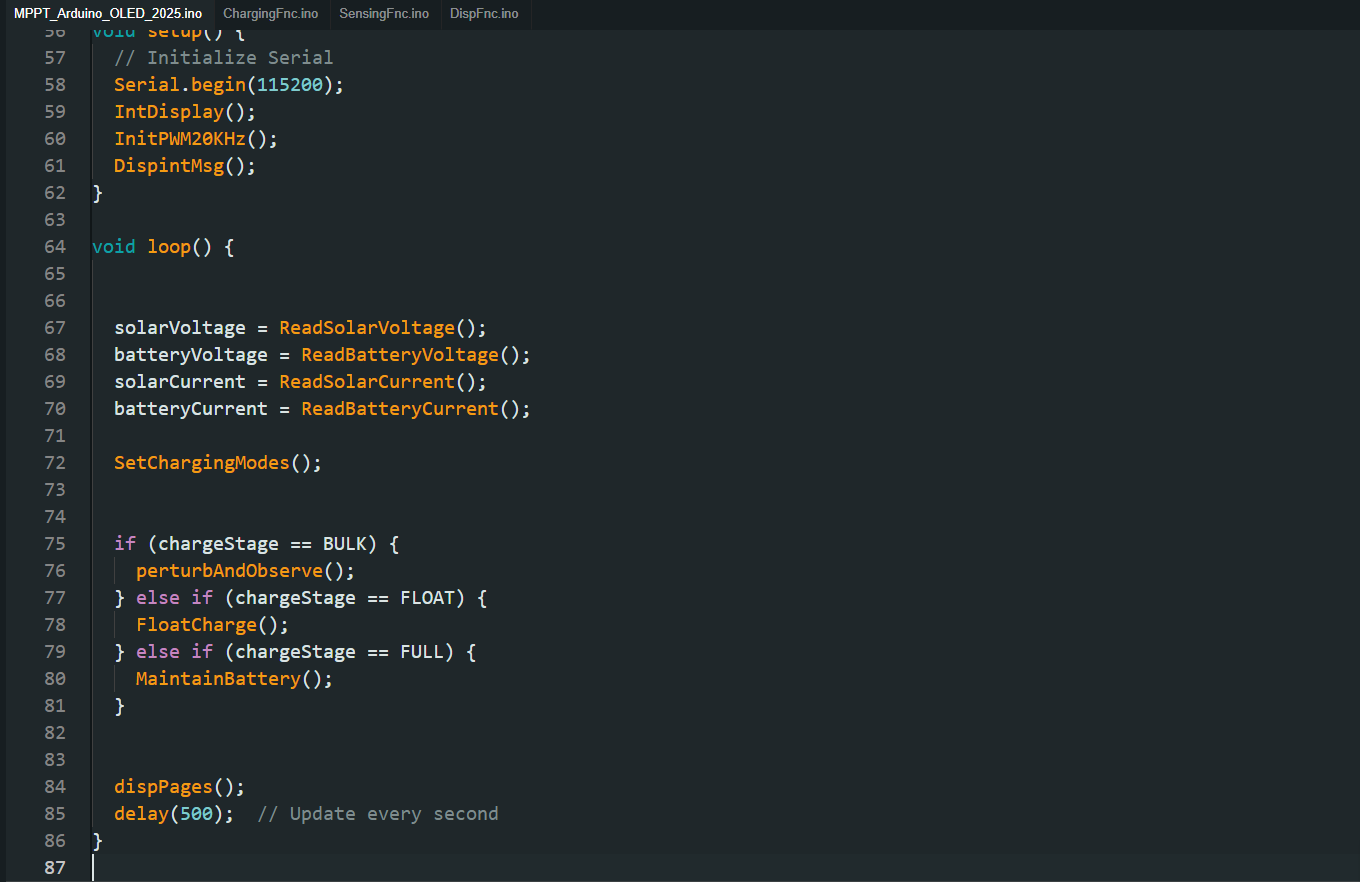
void setup() {
// Initialize Serial
Serial.begin(115200);
IntDisplay();
InitPWM20KHz();
DispintMsg();
}
void loop() {
solarVoltage = ReadSolarVoltage();
batteryVoltage = ReadBatteryVoltage();
solarCurrent = ReadSolarCurrent();
batteryCurrent = ReadBatteryCurrent();
SetChargingModes();
if (chargeStage == BULK) {
perturbAndObserve();
} else if (chargeStage == FLOAT) {
FloatCharge();
} else if (chargeStage == FULL) {
MaintainBattery();
}
dispPages();
delay(500); // Update every second
}
Code explanation:
#include <Adafruit_SSD1306.h> and #include "Wire.h"
These libraries are included to control the OLED display using the I2C protocol.
Then,
#define SCREEN_WIDTH 128
#define SCREEN_HEIGHT 32
#define OLED_RESET -1
#define SCREEN_ADDRESS 0x3C
Adafruit_SSD1306 display(SCREEN_WIDTH, SCREEN_HEIGHT, &Wire, OLED_RESET);
This initializes the OLED display with a resolution of 128×32 pixels and the I2C address 0x3C.
After that, there are some other variables for different purposes. Comments are already there.
In the main loop(),
void loop() {
  solarVoltage = ReadSolarVoltage();
  batteryVoltage = ReadBatteryVoltage();
  solarCurrent = ReadSolarCurrent();
  batteryCurrent = ReadBatteryCurrent();

  SetChargingModes();

  if (chargeStage == BULK) {
    perturbAndObserve();
  } else if (chargeStage == FLOAT) {
    FloatCharge();
  } else if (chargeStage == FULL) {
    MaintainBattery();
  }

  dispPages();
  delay(500);
}
Reading Sensor Data:
ReadSolarVoltage(), ReadBatteryVoltage(), ReadSolarCurrent(), and ReadBatteryCurrent() are functions (not shown here) that read analog data from the respective sensors to determine the solar panel’s and battery’s voltage and current.
Charging Mode Selection:
SetChargingModes() determines the current charging stage based on voltage, current, and thresholds.
Bulk Charging:
In the Bulk mode, the MPPT algorithm perturbAndObserve() is applied to extract the maximum power from the solar panel.
Float Charging:
If the battery voltage reaches the Bulk threshold, the system switches to Float mode using FloatCharge(), reducing current and maintaining a safe battery voltage.
Full Charging:
Once the battery reaches the float limits, the system enters the Full stage, where MaintainBattery() is used to ensure the battery remains charged and stable.
Display Update:
dispPages() updates the OLED display with system parameters (voltage, current, charge mode, etc.).
The loop has a delay of 500ms, meaning the display and calculations update every half a second.
Charging Modes in Detail:
- Bulk Mode:
The MPPT algorithm perturbs the PWM duty cycle to track the maximum power point of the solar panel. - Float Mode:
The charging current is reduced, and the battery voltage is maintained between 13.6V to 13.8V. - Full Mode:
After float charging, the battery is monitored. If the voltage drops below a specific threshold, the system restarts the charging process.
Now, the other codes are on different pages.
Let’s test the project.
Testing of our MPPT controller using Arduino:
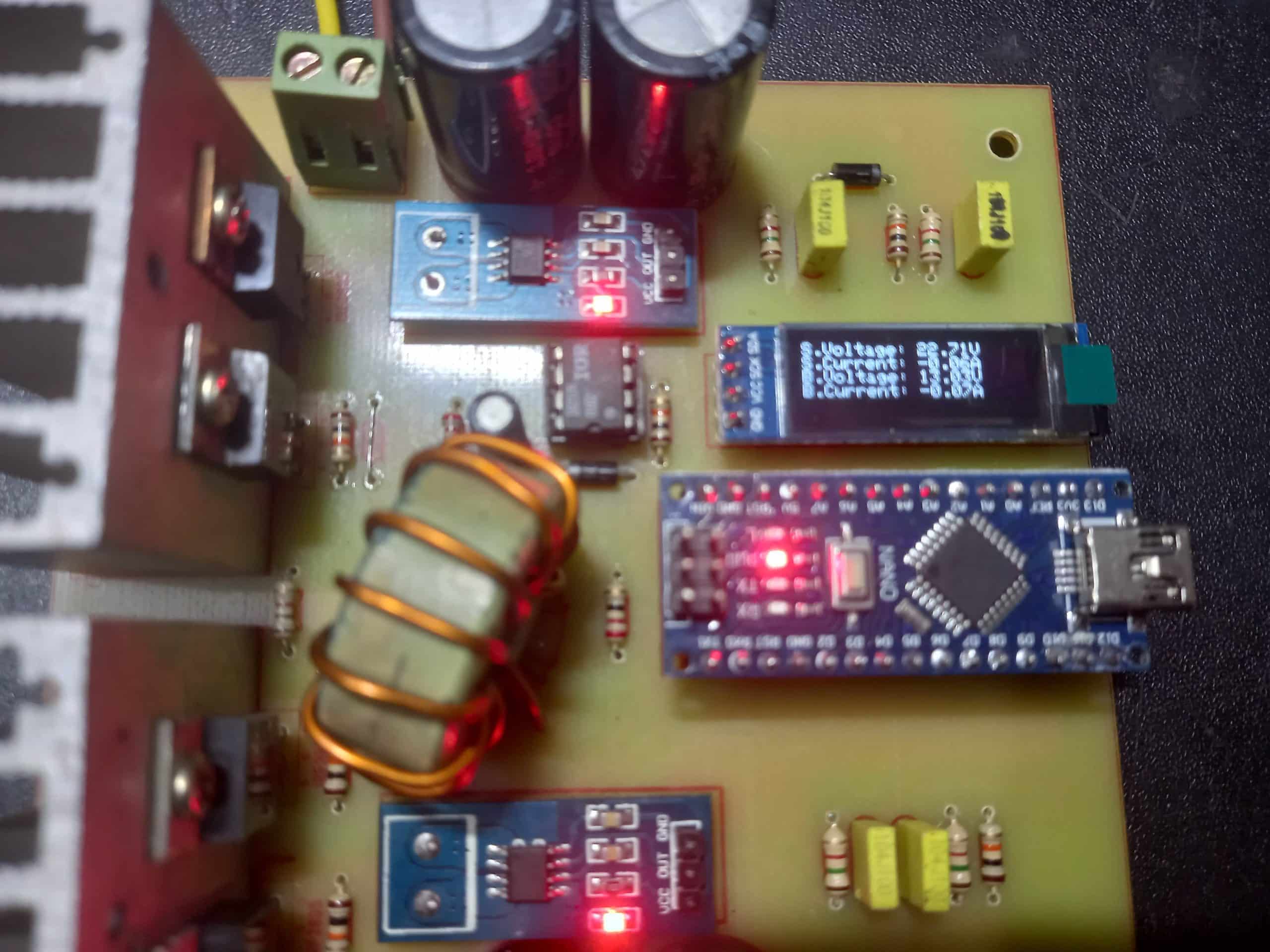
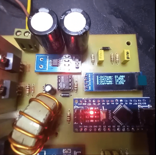
Overall, the controller is working fine. The project is designed to make a bigger version of this. If you are interested, let me know.
Conclusion:
In this article, I have explained how to build an MPPT controller using Arduino, step by step, with detailed information. I hope this project will be highly beneficial for you. As a professional with extensive experience in similar projects, I’m confident in delivering high-quality solutions.
If you’re interested or have any questions, feel free to contact me!
Liked this article? Subscribe to our newsletter:
or,
Visit LabProjectsBD.com for more inspiring projects and tutorials.
Thank you!
Read more:
- Building a CAN Bus Simulator with MCP2515 and Arduino
- How to implement a maximum power point tracking (MPPT) algorithm with an Arduino
- Guide to design low-power IoT devices: Maximizing Battery Life
- 6V Lead-Acid battery charger circuit
- A smart Battery charger circuit design guide
- How to implement a maximum power point tracking (MPPT) algorithm with an Arduino
See you again!


37 Comments
CHIMEZIE · 01/02/2025 at 1:23 am
thank you very much for this project, please i will love to build this MPPT unit but i have some questions
1. the code dose not mention the allowed max charging current, so how dose the system chooses the correct current during bulk charge.
2. to increase the solar input voltage to 80 volts what do i need to change in the circuit apart from R8 and R9 voltage divider, also what has to change in the code to achieve this new input voltage level,, thanks..
MKDas · 02/02/2025 at 11:29 am
Thank you for your comment. Designing for higher voltage and current ranges requires careful attention to additional protective measures and voltage conversion stages.
Current Range: There’s no specific limit on the maximum current in the code. The key is selecting a solar panel with the appropriate power (wattage) rating. The MPPT algorithm will always attempt to extract the maximum possible power from the panel.
High-Voltage Input (e.g., 80V):
Inductor (Coil) Design: Ensure the coil is optimized for higher voltages and currents.
MOSFET Selection: Choose MOSFETs with adequate voltage and current ratings, low Rds(on), and high efficiency.
Thermal Management: Use proper heat sinks and, if necessary, additional cooling fans.
Temperature Monitoring: Include temperature sensors to monitor and protect against overheating.
Power Supply and Voltage Sensing: Modify the power supply circuit and sensing stages to handle the higher voltage safely.
Firmware Adjustments: Update code variables to accommodate higher operating ranges.
If you need professional assistance, feel free to contact me on WhatsApp.
CHIMEZIE · 02/03/2025 at 10:42 pm
Engineer thank you very much for your reply,
I have been struggling to understand your MOSFETs configuration in the schematic,
example gates off Q1 and Q4 are linked together from a single resistance R2 of 22ohm ,
also Q4 have a higher gate resistance of 1k, is this an error or not? Please how does it work.. thanks
MKDas · 04/03/2025 at 11:40 am
Well, thats the interesting part of this design. Those MOSFETs are used as Diode and while the Main switch Q2 is switched on, those are also. But while Q3 is also acting as a synchronous diode, those two are kept off to prevent short circuit.
Usually, people do not use Q4. But I use in my practical designs to reduce heat loss. Q4 gate resistance is higher, because the signal is already boosts by IR2104. To keep it under Vgs range, resistors are used.
I hope you got it now.
CHIMEZIE · 10/03/2025 at 2:14 am
Engineer thank you for replying, I now understand,
One final observation in the circuit the gate resistor 22ohm R2 is shared by Q1 and Q2 and not separate,
Please why are they not using separate gate resistors?
MKDas · 10/03/2025 at 11:59 am
No needed. but if you want to use extra resistor, you can use
Enrique · 02/02/2025 at 9:42 pm
Excelente trabajo ,soy aficionado a la electrónica todo lo que tiene que ver con fuentes me interesa mucho y estas publicaciones me ayudan mucho para entender de forma practica el funcionamiento. muchas gracias, sigo todas sus publicaciones
MKDas · 04/02/2025 at 11:15 am
Thank you! 👍👍👍
PAUL · 02/03/2025 at 11:04 pm
Please am having issues designing this
C1 is 10uf, what is the voltage of C1..?
Also can i use 1N4148 for D1…?
Finally I noticed that R3 and R4 are directly connected to the gate of Q3… Please is the connection correct or an error?
MKDas · 04/03/2025 at 11:41 am
use 25 or 50v one for C1. And for diode, use any fast diode that can support minimum 50KHz. R3 and R4 are correct.
Ige Daniel · 30/04/2025 at 1:05 am
I got the inductor calculations but I have difficulty in designing the appropriate one, not giving the expected results, please kindly help.
MKDas · 01/05/2025 at 1:15 pm
Try few times.
Oscar · 06/05/2025 at 4:26 pm
I am interested in this project, but I want to know if the IR2104 is connected correctly. I have no experience with 2104 before. I found that the Vcc port of IR2104 is not connected to any input power source in the circuit diagram.
MKDas · 06/05/2025 at 6:06 pm
If you are using 12V setup then connect that VCC pin to solar positive. if you use 24V setup, then connect that to B+ with a 100R 0.5W Resistor.
Paul · 06/10/2025 at 9:55 pm
Hello sir, please I have an issue, Q4 heats up rapidly and output efficiency is around 75%, please what could be the issue and did you encounter this behavior too, please suggest a solution for me.. thanks
MKDas · 07/10/2025 at 12:03 pm
Check the Vgs of Q4. Also ensure Rgs is not less than 10K.
Paul · 15/10/2025 at 1:09 am
Sir please is it also important to reduce R6 to a lower resistance value..? To enable full switching of Q4.. and finally Sir please what is the expected efficiency from your experience…?
MKDas · 16/10/2025 at 12:26 pm
R6 used for noise filtering. use minimum 10K max 100K
Paul · 17/10/2025 at 9:20 pm
Thanks for your quick reply sir,
Please check the circuit again as R6 is actually 1k (gate resistor).. my question is don’t you think the 1k is preventing Q4 from switching fully..?
MKDas · 18/10/2025 at 1:02 pm
not really. just use high pull down resistor.
noop K A · 18/10/2025 at 2:15 pm
sir code uploading error
Compilation error: ‘IntDisplay’ was not declared in this scope
MKDas · 22/10/2025 at 12:29 pm
Check if you missed the file
Anoop k A · 18/10/2025 at 11:58 pm
I made this circuit but i can’t upload code compiling error please send the code
MKDas · 22/10/2025 at 12:29 pm
send your erros images to WhatsApp
Ben · 29/10/2025 at 7:19 am
Hello sir, please I have a question. First, does the Arduino’s GND need to be connected to the IR2104’s COM? And second, can I use a Fully 12V 7Ah lead-acid battery as a load directly? Will it draw current? Please suggest a solution for me. Thanks
MKDas · 01/11/2025 at 11:42 am
both arduino and IR2104 GND / COM are common.
you can use 12V lead acid batteries in the place of BAT
Ben · 02/11/2025 at 10:06 am
Thank you for your reply.
I have a few more questions that I would like to ask for your advice on.
First, can I use a power supply instead of a solar panel for testing purposes?
Also, if I use an LM2596 step-down module to convert a Vin of 18V down to 12V, would it be suitable to supply power to both the IR2104 and a 7805 regulator for the Arduino?
MKDas · 02/11/2025 at 6:53 pm
if you use power supply, it will draw the max possible output from power supply. yes you can use it but it will show the power supply is always at high amp output.
and you can use LM2596 for DC/DC no issue.
Ben · 04/11/2025 at 8:38 pm
The code you uploaded can’t be used as is yet, right? It still needs configuration in the sections for Reading Sensor Data and Charging Mode Selection, such as the voltage divider circuit or the ACS712.
MKDas · 06/11/2025 at 12:08 pm
if you change in the hardware then you must configure that properly.
Selasi · 09/11/2025 at 9:29 pm
I have a feeling that leading international company you work at is Tesla.
Rainto · 19/12/2025 at 11:41 am
Hi, Please need full code if available. Thank you
MKDas · 19/12/2025 at 12:02 pm
Full code is give here.
Nono · 16/01/2026 at 8:36 pm
Hi!
I would like to create this MPPT regulator for a school project in which I am trying to compare the charge of a 3S lithium battery with a solar panel with and without a regulator. So I was wondering if it was possible to create it for a fairly high panel output voltage (40V). I don’t know much about electronics, should these components be connected to a microlab board?
Thank you for your help.
MKDas · 17/01/2026 at 2:16 pm
That is totally risky. But if you understand the concept, then you can design the buck converter to convert incoming voltage to suitable output range for your cells. then control using the algorithm
Saurabh sharma · 07/02/2026 at 8:48 pm
Sir, if we use synchronous half bridge design to make buck mppt, when connect battery on output it makes spikes like short circuit and blows mosfets or fuses, if we run from solar first then conne t battery it works well. How can i solve this issue? I am not using q4 as like you.
MKDas · 13/02/2026 at 12:15 pm
because of the diode. check you are not using any diode on the output. if you don’t use any diode, the lower switch will short the battery through inductor. so it will get burnt itself.