In this article, we’ll walk you through the steps to create a WiFi-controlled relay using the NodeMCU v3, an excellent microcontroller board based on the ESP8266 WiFi module. This project allows you to control electrical devices remotely over a WiFi network using a web interface. Let’s dive into the details.
⚠️Disclaimer:
Working with electricity involves serious risk. Ensure you have the necessary skills and take proper safety precautions before attempting any electrical projects. Proceed at your own risk — the author assumes no responsibility for any damage, injury, or issues resulting from the use or misuse of the information provided.
All content on this website is original and protected by copyright. Please do not copy or reproduce content without permission. While most of the resources shared here are open-source and freely accessible for your learning and benefit, your respect for our intellectual effort is appreciated.
If you find our tutorials helpful, consider supporting us by purchasing related materials or sharing our work — it helps keep the content flowing.
Need help or have questions? Leave a comment below — the author is always happy to assist!
There are lots of Wi-Fi remote switches available in the market. It is not tough to make of your own. Let’s see what we need to make such a control.
Table of Contents
Components Needed:
- NodeMCU v3 (ESP8266)
- Relay Module
- Jumper Wires
- Breadboard
- USB Cable
- 5V Power Supply (optional, depending on your relay module)
- Electrical Device (e.g., a light bulb or a fan)
You may have some of these components already, that you can use. But it is just a common list.
Understanding the Components:
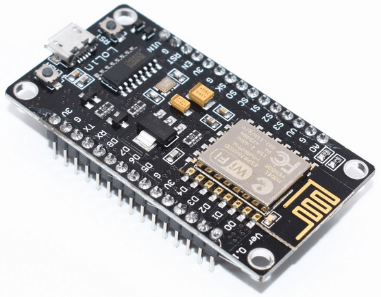
NodeMCU v3 (ESP8266): The NodeMCU v3 is a low-cost WiFi microcontroller with GPIO (General Purpose Input/Output) pins, making it ideal for IoT applications.
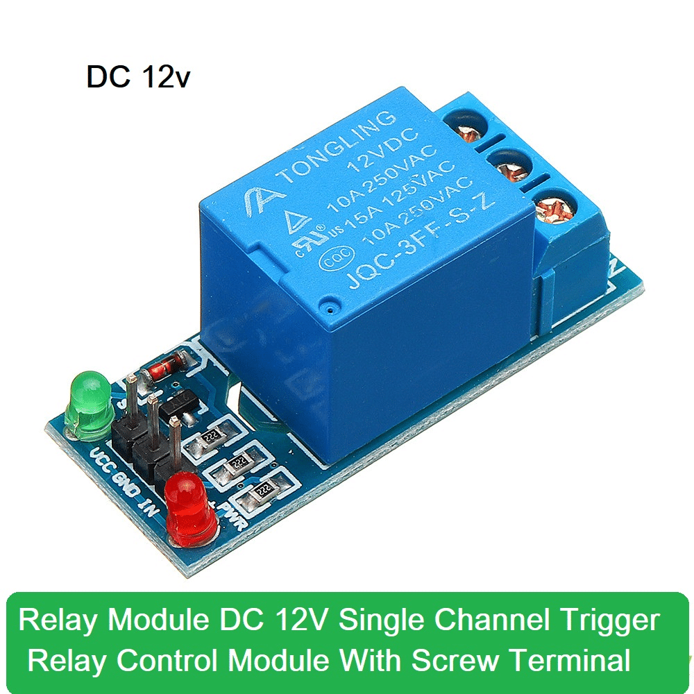
Relay Module: A relay is an electrically operated switch that allows you to control high-voltage devices (e.g., home appliances) with a low-voltage signal from the NodeMCU. You can use a relay in the PCB or circuit with a transistor or similar switching device. But a module makes the work easier for quick testing.
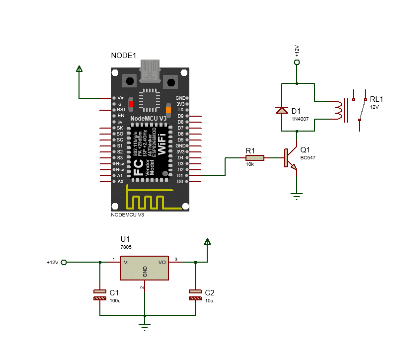
Circuit diagram:
Setting Up the Hardware:
Connect the relay module or relay to the digital I/O pin D1 of the NodeMCU using a jumper wire. If you use a relay without a module, follow the circuit diagram above. Provide power to the NodeMCU by plugging in the USB cable or using another suitable power source.
Writing the Code
The following Arduino code sets up a web server on the NodeMCU to control the relay via a web browser.
Installing Libraries: Before uploading the code, ensure you have the following libraries installed in your Arduino IDE:
#include <ESP8266WiFi.h>
#include <ESP8266WebServer.h>
const char* ssid = "Your_SSID";
const char* password = "Your_PASSWORD
ESP8266WebServer server(80);
const int relayPin = D1; // GPIO5
void setup() {
Serial.begin(115200);
WiFi.begin(ssid, password);
Serial.println("Looking for SSID...");
// Wait for connection
while (WiFi.status() != WL_CONNECTED) {
delay(500);
Serial.print(".");
}
Serial.println("");
Serial.print("Connected to ");
Serial.println(ssid);
Serial.print("IP address: ");
Serial.println(WiFi.localIP());
pinMode(relayPin, OUTPUT);
digitalWrite(relayPin, HIGH); // Start with the relay off
server.on("/", handleRoot);
server.on("/on", handleRelayOn);
server.on("/off", handleRelayOff);
server.begin();
Serial.println("HTTP server started");
}
void handleRoot() {
server.send(200, "text/html", "<h1>WiFi Relay Control</h1><p><a href=\"/on\">Turn On</a></p><p><a href=\"/off\">Turn Off</a></p>");
}
void handleRelayOn() {
digitalWrite(relayPin, LOW);
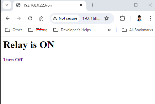
server.send(200, "text/html", "<h1>Relay is ON</h1><p><a href=\"/off\"><b>Turn Off</b></a></p>");
Serial.println("Relay:OFF");
}
void handleRelayOff() {
digitalWrite(relayPin, HIGH);
server.send(200, "text/html", "<h1>Relay is OFF</h1><p><a href=\"/on\"><b>Turn On</b></a></p>");
Serial.println("Relay:ON");
}
void loop() {
server.handleClient();
}
Explanation of Code:
This code sets up a NodeMCU (ESP8266) as a web server to control a relay connected to pin D1. The relay can be turned on or off via a web interface. Here’s a detailed explanation of the code:
Libraries
#include <ESP8266WiFi.h>
#include <ESP8266WebServer.h>
These libraries are essential for connecting to a Wi-Fi network and setting up a web server on the ESP8266.
Wi-Fi Credentials
const char* ssid = "Your_SSID";
const char* password = "Your_PASSWORD";
These are the credentials for the Wi-Fi network to which the ESP8266 will connect. Replace Your_SSID and Your_PASSWORD with your actual Wi-Fi network name and password.
Web Server Setup
ESP8266WebServer server(80);
This initializes a web server object on port 80, the default HTTP port.
Pin Configuration
const int relayPin = D1; // GPIO5
This sets relayPin to D1, which corresponds to GPIO5 on the ESP8266.
Setup Function
void setup() {
  Serial.begin(115200);
  WiFi.begin(ssid, password);
  Serial.println("");

  // Wait for connection
  while (WiFi.status() != WL_CONNECTED) {
    delay(500);
    Serial.print(".");
  }
  Serial.println("");
  Serial.print("Connected to ");
  Serial.println(ssid);
  Serial.print("IP address: ");
  Serial.println(WiFi.localIP());

  pinMode(relayPin, OUTPUT);
  digitalWrite(relayPin, HIGH); // Start with the relay off

  server.on("/", handleRoot);
  server.on("/on", handleRelayOn);
  server.on("/off", handleRelayOff);

  server.begin();
  Serial.println("HTTP server started");
}
- Serial Communication: Starts serial communication at a baud rate of 115200 for debugging.
- Wi-Fi Connection: Connects to the specified Wi-Fi network. The while loop continuously checks the connection status and prints dots (
.) until connected. - Debug Info: Once connected, it prints the SSID and the IP address assigned to the ESP8266.
- Pin Initialization: Sets
relayPinas an output and initializes it to HIGH (relay off). - Server Routes: Defines URL routes:
/: Root route handled byhandleRoot./on: Turns the relay on, handled byhandleRelayOn./off: Turns the relay off, handled byhandleRelayOff.
- Server Start: Starts the web server and prints a confirmation message.
Handle Root
void handleRoot() {
  server.send(200, "text/html", "<h1>WiFi Relay Control</h1><p><a href=\"/on\">Turn On</a></p><p><a href=\"/off\">Turn Off</a></p>");
}
This function serves the main page with links to turn the relay on and off. The page is returned as HTML.
Handle Relay On
void handleRelayOn() {
  digitalWrite(relayPin, LOW);
  server.send(200, "text/html", "<h1>Relay is ON</h1><p><a href=\"/off\">Turn Off</a></p>");
}
This function turns the relay on by setting relayPin to LOW and sends a response indicating the relay is on with a link to turn it off.
Handle Relay Off
void handleRelayOff() {
  digitalWrite(relayPin, HIGH);
  server.send(200, "text/html", "<h1>Relay is OFF</h1><p><a href=\"/on\">Turn On</a></p>");
}
This function turns the relay off by setting relayPin to HIGH and sends a response indicating the relay is off with a link to turn it on.
Loop Function
void loop() {
  server.handleClient();
}
This function continuously handles incoming client requests to the web server, ensuring the web interface remains responsive.
Testing the hardware:
Now run the system after putting your SSID and password. Then it will connect to the SSID and give you an IP address to access.
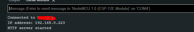
Copy that IP address to the browser and boom!
Here is the corrected and refined version of your statement:
“And now you can experiment with this setup. Let’s start by connecting an LED to check if the pin is working correctly.”
Result:
Conclusion:
This project demonstrates how to use the NodeMCU v3 and a relay module to control electrical devices over WiFi. By following the steps and using the provided code, you can create a robust and flexible system to automate various tasks in your home or office.
Liked this article? Subscribe to our newsletter:
or,
Visit LabProjectsBD.com for more inspiring projects and tutorials.
Thank you!
Read more:


0 Comments