Learn how to interface a 7-segment display with STM32 microcontroller in this article. We cover the basics of 7-segment display operation, connection to the STM32, and programming using STM32CubeIDE. Get started with this beginner-friendly guide!
⚠️Disclaimer:
Working with electricity involves serious risk. Ensure you have the necessary skills and take proper safety precautions before attempting any electrical projects. Proceed at your own risk — the author assumes no responsibility for any damage, injury, or issues resulting from the use or misuse of the information provided.
All content on this website is original and protected by copyright. Please do not copy or reproduce content without permission. While most of the resources shared here are open-source and freely accessible for your learning and benefit, your respect for our intellectual effort is appreciated.
If you find our tutorials helpful, consider supporting us by purchasing related materials or sharing our work — it helps keep the content flowing.
Need help or have questions? Leave a comment below — the author is always happy to assist!
Table of Contents
About 7-Segment display:
A seven-segment display is a form of an electronic display device for displaying decimal numerals that is an alternative to the more complex dot matrix displays.
Seven-segment displays are widely used in digital clocks, electronic meters, basic calculators, and other electronic devices that display numerical information
The seven segments are arranged as a rectangle of two vertical segments on each side with one horizontal segment on the top, middle, and bottom. Often the rectangle is oblique (slanted), which aids readability.[citation needed] In most applications, the segments are of nearly uniform shape and size (usually elongated hexagons, though trapezoids and rectangles can also be used), though in the case of adding machines, the vertical segments are longer and more oddly shaped at the ends in an effort to further enhance readability. The seven elements of the display can be lit in different combinations to represent the Arabic numerals.
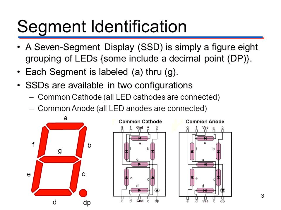
The segments are referred to by the letters A to G, where the optional decimal point (an “eighth segment”, referred to as DP) is used for the display of non-integer numbers. A single byte can encode the full state of a 7-segment display including the decimal point. The most popular bit encodings are gfedcba and abcdefg. In the gfedcba representation, a byte value of 0x06 would turn on segments “c” and “b”, which would display a “1”.
Types of Seven-Segment Displays:
There are two types of seven-segment displays such as common anode and common cathode.
Common Anode Display:
In a common anode display, all the anode terminals of eight light-emitting diodes are common and connect with a 5-volt power supply. In normal conditions, we apply logic high from our microcontroller to each segment. Therefore, each segment remains off or does not glow. Similarly, when we want to turn on a specific LED of a seven-segment device, we provide a logic low signal. Because LED glows only when there will be a logic high signal on the anode side and a logic low signal on the cathode side such is the case of a common anode type display.
Common Cathode Display:
In the common cathode segment display, all the cathodes of eight light-emitting diodes are common and connect with the ground. In order to turn off any segment of 7-segment, we apply logic low from our microcontroller to this segment. Similarly, when we want to turn on a specific LED of a seven-segment device, we provide a logic high signal from the microcontroller digital output pin. Because LED glows only when there will be a logic high signal on the anode side and a logic low signal on the cathode side such is the case of a common cathode-type display.
Now, how multiplexing works:
Multiple-digit LED displays as used in pocket calculators and similar devices used multiplexed displays to reduce the number of I/O pins required to control the display. For example, all the anodes of the A segments of each digit position would be connected together and to a driver circuit pin, while the cathodes of all segments for each digit would be connected. To operate any particular segment of any digit, the controlling integrated circuit would turn on the cathode driver for the selected digit, and the anode drivers for the desired segments; then after a short blanking interval the next digit would be selected and new segments lit, in a sequential fashion. In this manner, an eight-digit display with seven segments and a decimal point would require only 8 cathode drivers and 8 anode drivers, instead of sixty-four drivers and IC pins. Often in pocket calculators, the digit drive lines would be used to scan the keyboard as well, providing further savings; however, pressing multiple keys at once would produce odd results on the multiplexed display.
Although to the naked eye, all digits of an LED display appear lit, only one digit is lit at any given time in a multiplexed display. The digit changes at a high enough rate that the human eye cannot see the flashing (on earlier devices it could be visible to peripheral vision).
Interfacing with STM32:
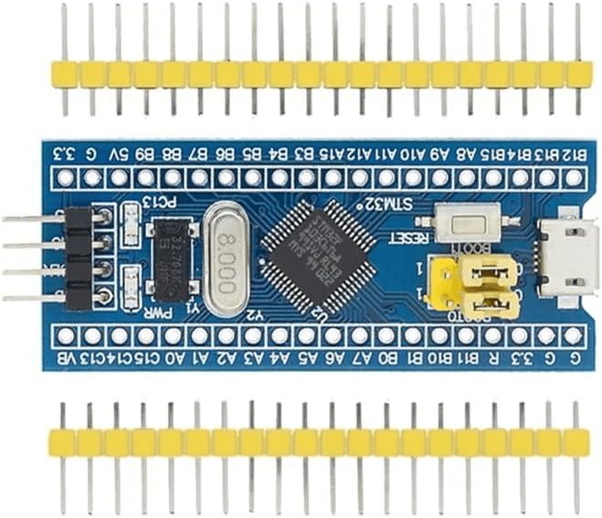
The STM32 Blue Pill is a small development board that is based on the powerful STM32 microcontroller. This board is a cost-effective and powerful solution for developing embedded systems. It is ideal for hobbyists and students who want to learn about microcontrollers and embedded systems. In this article, we will discuss how to interface a 4-digit 7-segment display with the STM32 Blue Pill using STM32CubeIDE.
Prerequisites:
Before we begin, we need to have the following items:
STM32CubeIDE is a software tool that helps in developing applications for STM32 microcontrollers. It includes a graphical user interface (GUI) for configuration, code generation, and debugging.
Hardware Setup:
The 4-digit 7-segment display has 12 pins, 4 for the common cathode pins, and 8 for the segment pins. The common cathode pins are connected to the ground, and the segment pins are connected to the STM32 Blue Pill board. The segment pins are connected to the following pins of the STM32 Blue Pill board:
- Segment A -> PB3
- Segment B -> PB4
- Segment C -> PB5
- Segment D -> PB6
- Segment E -> PB7
- Segment F -> PB8
- Segment G -> PB9
- Segment DP -> PB10
The common cathode pins of the 4-digit 7-segment display are connected to the following pins of the STM32 Blue Pill board:
- Digit 1 -> PA0
- Digit 2 -> PA1
- Digit 3 -> PA2
- Digit 4 -> PA3
Software Setup:
To program the STM32 Blue Pill board, we need to use STM32CubeIDE. We will create a new project in STM32CubeIDE and configure it to work with the STM32 Blue Pill board. We will then write the code to display numbers on the 4-digit 7-segment display.
- Create a new project in STM32CubeIDE:
- Open STM32CubeIDE.
- Click on File -> New -> STM32 Project.
- Choose the microcontroller that you are using (in our case, STM32F103C8).
- Enter a name for the project and choose a location to save it.
- Click on Finish.
- Configure the project to work with the STM32 Blue Pill board:
- Open the Pinout & Configuration tab.
- Choose the STM32 Blue Pill board from the Board selector.
- Configure the pins as follows:
- PA0 -> GPIO_Output (Output push-pull, Max Speed 50MHz)
- PA1 -> GPIO_Output (Output push-pull, Max Speed 50MHz)
- PA2 -> GPIO_Output (Output push-pull, Max Speed 50MHz)
- PA3 -> GPIO_Output (Output push-pull, Max Speed 50MHz)
- PB3 -> GPIO_Output (Output push-pull, Max Speed 50MHz)
- PB4 -> GPIO_Output (Output push-pull, Max Speed 50MHz)
- PB5 -> GPIO_Output (Output push-pull, Max Speed 50MHz)
- PB6 -> GPIO_Output (Output push-pull, Max Speed 50MHz)
- PB7 -> GPIO_Output (Output push-pull, Max Speed 50MHz)
- PB8 -> GPIO_Output (Output push-pull, Max Speed 50MHz)
- PB9 -> GPIO_Output (Output push-pull, Max Speed 50MHz)
- PB10 -> GPIO_Output (Output push-pull, Max Speed 50MHz)
- Write the code to display numbers on the 4-digit 7-segment display:
- Open the main.c file in the Src folder.
- Write the following code in the main function:
#include "stm32f1xx_hal.h"

void displayDigit(int digit, int value);
void displayNumber(int number);

int main(void)
{
	HAL_Init();

	GPIO_InitTypeDef GPIO_InitStruct;
	__HAL_RCC_GPIOA_CLK_ENABLE();
	__HAL_RCC_GPIOB_CLK_ENABLE();

	GPIO_InitStruct.Pin = GPIO_PIN_0 | GPIO_PIN_1 | GPIO_PIN_2 | GPIO_PIN_3;
	GPIO_InitStruct.Mode = GPIO_MODE_OUTPUT_PP;
	GPIO_InitStruct.Speed = GPIO_SPEED_FREQ_HIGH;
	HAL_GPIO_Init(GPIOA, &GPIO_InitStruct);

	GPIO_InitStruct.Pin = GPIO_PIN_3 | GPIO_PIN_4 | GPIO_PIN_5 | GPIO_PIN_6
			| GPIO_PIN_7 | GPIO_PIN_8 | GPIO_PIN_9 | GPIO_PIN_10;
	GPIO_InitStruct.Mode = GPIO_MODE_OUTPUT_PP;
	GPIO_InitStruct.Speed = GPIO_SPEED_FREQ_HIGH;
	HAL_GPIO_Init(GPIOB, &GPIO_InitStruct);

	while (1)
	{
		displayNumber(1234);
		HAL_Delay(1000);
		displayNumber(5678);
		HAL_Delay(1000);
	}
}

void displayDigit(int digit, int value)
{
	switch (digit)
	{
	case 1:
		HAL_GPIO_WritePin(GPIOA, GPIO_PIN_0, GPIO_PIN_SET);
		break;
	case 2:
		HAL_GPIO_WritePin(GPIOA, GPIO_PIN_1, GPIO_PIN_SET);
		break;
	case 3:
		HAL_GPIO_WritePin(GPIOA, GPIO_PIN_2, GPIO_PIN_SET);
		break;
	case 4:
		HAL_GPIO_WritePin(GPIOA, GPIO_PIN_3, GPIO_PIN_SET);
		break;
	}

	switch (value)
	{
	case 0:
		HAL_GPIO_WritePin(GPIOB,
				GPIO_PIN_3 | GPIO_PIN_4 | GPIO_PIN_5 | GPIO_PIN_6 | GPIO_PIN_7
						| GPIO_PIN_8, GPIO_PIN_SET);
		HAL_GPIO_WritePin(GPIOB, GPIO_PIN_9 | GPIO_PIN_10, GPIO_PIN_RESET);
		break;
	case 1:
		HAL_GPIO_WritePin(GPIOB, GPIO_PIN_6 | GPIO_PIN_8, GPIO_PIN_SET);
		HAL_GPIO_WritePin(GPIOB,
				GPIO_PIN_3 | GPIO_PIN_4 | GPIO_PIN_5 | GPIO_PIN_7 | GPIO_PIN_9
						| GPIO_PIN_10, GPIO_PIN_RESET);
		break;
	case 2:
		HAL_GPIO_WritePin(GPIOB,
				GPIO_PIN_5 | GPIO_PIN_6 | GPIO_PIN_7 | GPIO_PIN_8 | GPIO_PIN_9,
				GPIO_PIN_SET);
		HAL_GPIO_WritePin(GPIOB, GPIO_PIN_3 | GPIO_PIN_4 | GPIO_PIN_10,
				GPIO_PIN_RESET);
		break;
	case 3:
		HAL_GPIO_WritePin(GPIOB,
				GPIO_PIN_4 | GPIO_PIN_5 | GPIO_PIN_6 | GPIO_PIN_7 | GPIO_PIN_9,
				GPIO_PIN_SET);
		HAL_GPIO_WritePin(GPIOB, GPIO_PIN_3 | GPIO_PIN_8 | GPIO_PIN_10,
				GPIO_PIN_RESET);
		break;
	case 4:
		HAL_GPIO_WritePin(GPIOB,
				GPIO_PIN_3 | GPIO_PIN_6 | GPIO_PIN_7 | GPIO_PIN_9,
				GPIO_PIN_SET);
		HAL_GPIO_WritePin(GPIOB,
				GPIO_PIN_4 | GPIO_PIN_5 | GPIO_PIN_8 | GPIO_PIN_10,
				GPIO_PIN_RESET);
		break;
	case 5:
		HAL_GPIO_WritePin(GPIOB,
				GPIO_PIN_4 | GPIO_PIN_5 | GPIO_PIN_6 | GPIO_PIN_8 | GPIO_PIN_9,
				GPIO_PIN_SET);
		HAL_GPIO_WritePin(GPIOB, GPIO_PIN_3 | GPIO_PIN_7 | GPIO_PIN_10,
				GPIO_PIN_RESET);
		break;
	case 6:
		HAL_GPIO_WritePin(GPIOB,
				GPIO_PIN_4 | GPIO_PIN_5 | GPIO_PIN_6 | GPIO_PIN_7 | GPIO_PIN_8
						| GPIO_PIN_9, GPIO_PIN_SET);
		HAL_GPIO_WritePin(GPIOB, GPIO_PIN_3 | GPIO_PIN_10, GPIO_PIN_RESET);
		break;
	case 7:
		HAL_GPIO_WritePin(GPIOB,
				GPIO_PIN_3 | GPIO_PIN_4 | GPIO_PIN_5 | GPIO_PIN_8,
				GPIO_PIN_SET);
		HAL_GPIO_WritePin(GPIOB,
				GPIO_PIN_6 | GPIO_PIN_7 | GPIO_PIN_9 | GPIO_PIN_10,
				GPIO_PIN_RESET);
		break;
	case 8:
		HAL_GPIO_WritePin(GPIOB,
				GPIO_PIN_3 | GPIO_PIN_4 | GPIO_PIN_5 | GPIO_PIN_6 | GPIO_PIN_7
						| GPIO_PIN_8 | GPIO_PIN_9, GPIO_PIN_SET);
		HAL_GPIO_WritePin(GPIOB, GPIO_PIN_10, GPIO_PIN_RESET);
		break;
	case 9:
		HAL_GPIO_WritePin(GPIOB,
				GPIO_PIN_3 | GPIO_PIN_4 | GPIO_PIN_5 | GPIO_PIN_6 | GPIO_PIN_8
						| GPIO_PIN_9, GPIO_PIN_SET);
		HAL_GPIO_WritePin(GPIOB, GPIO_PIN_7 | GPIO_PIN_10, GPIO_PIN_RESET);
		break;
	}
}

void displayNumber(int number)
{
	int digit1 = number / 1000;
	int digit2 = (number / 100) % 10;
	int digit3 = (number / 10) % 10;
	int digit4 = number % 10;

	HAL_GPIO_WritePin(GPIOA, GPIO_PIN_0 | GPIO_PIN_1 | GPIO_PIN_2 | GPIO_PIN_3,
			GPIO_PIN_RESET);
	displayDigit(1, digit1);
	HAL_Delay(1);
	HAL_GPIO_WritePin(GPIOA, GPIO_PIN_0 | GPIO_PIN_1 | GPIO_PIN_2 | GPIO_PIN_3,
			GPIO_PIN_RESET);
	displayDigit(2, digit2);
	HAL_Delay(1);
	HAL_GPIO_WritePin(GPIOA, GPIO_PIN_0 | GPIO_PIN_1 | GPIO_PIN_2 | GPIO_PIN_3,
			GPIO_PIN_RESET);
	displayDigit(3, digit3);
	HAL_Delay(1);
	HAL_GPIO_WritePin(GPIOA, GPIO_PIN_0 | GPIO_PIN_1 | GPIO_PIN_2 | GPIO_PIN_3,
			GPIO_PIN_RESET);
	displayDigit(4, digit4);
	HAL_Delay(1);
}
- Build and run the code:
- Connect the STM32 Blue Pill board to your computer using a USB cable.
- Click on the Build icon in the toolbar to build the code.
- Click on the Run icon in the toolbar to run the code.
- You should see the numbers 1234 and 5678 being displayed on the 4-digit 7-segment display, with a delay of 1 second between each number.
Conclusion:
In this article, we have learned how to use the STM32 Blue Pill board with a 4-digit 7-segment display using STM32CubeIDE. We have written the code to display numbers on the 4-digit 7-segment display and have built and run the code. This is just simple.
Read more on:
- GLCD 128×64 ST7920 interfacing with STM32
- How to interface a 16×2 LCD with an STM32
- How to interface ESP8266 with STM32
- How to interface DHT11 with STM32
- STM32 Bluetooth Low Energy & its application
- How to interface the EM18 RFID module with STM32
Liked this article? Subscribe to our newsletter:
or,
Visit LabProjectsBD.com for more inspiring projects and tutorials.
Thank you!


0 Comments