Table of Contents
Introduction
A DC-DC converter is an essential component in modern electronics, used to step up or step-down voltage efficiently. High-efficiency designs are crucial in power-sensitive applications such as renewable energy systems, electric vehicles, industrial power supplies, and IoT devices.
This guide provides a step-by-step approach to designing a high-efficiency DC-DC converter, covering key aspects such as topology selection, component sizing, PCB design, and optimization techniques.
⚠️Disclaimer:
Working with electricity involves serious risk. Ensure you have the necessary skills and take proper safety precautions before attempting any electrical projects. Proceed at your own risk — the author assumes no responsibility for any damage, injury, or issues resulting from the use or misuse of the information provided.
All content on this website is original and protected by copyright. Please do not copy or reproduce content without permission. While most of the resources shared here are open-source and freely accessible for your learning and benefit, your respect for our intellectual effort is appreciated.
If you find our tutorials helpful, consider supporting us by purchasing related materials or sharing our work — it helps keep the content flowing.
Need help or have questions? Leave a comment below — the author is always happy to assist!
1. Understanding DC-DC Converter Topologies:
1.1 Types of DC-DC Converters
There are different types of DC-DC converters. At a glance, this is the chart if we can draw about types of DC-DC Converters in detail.
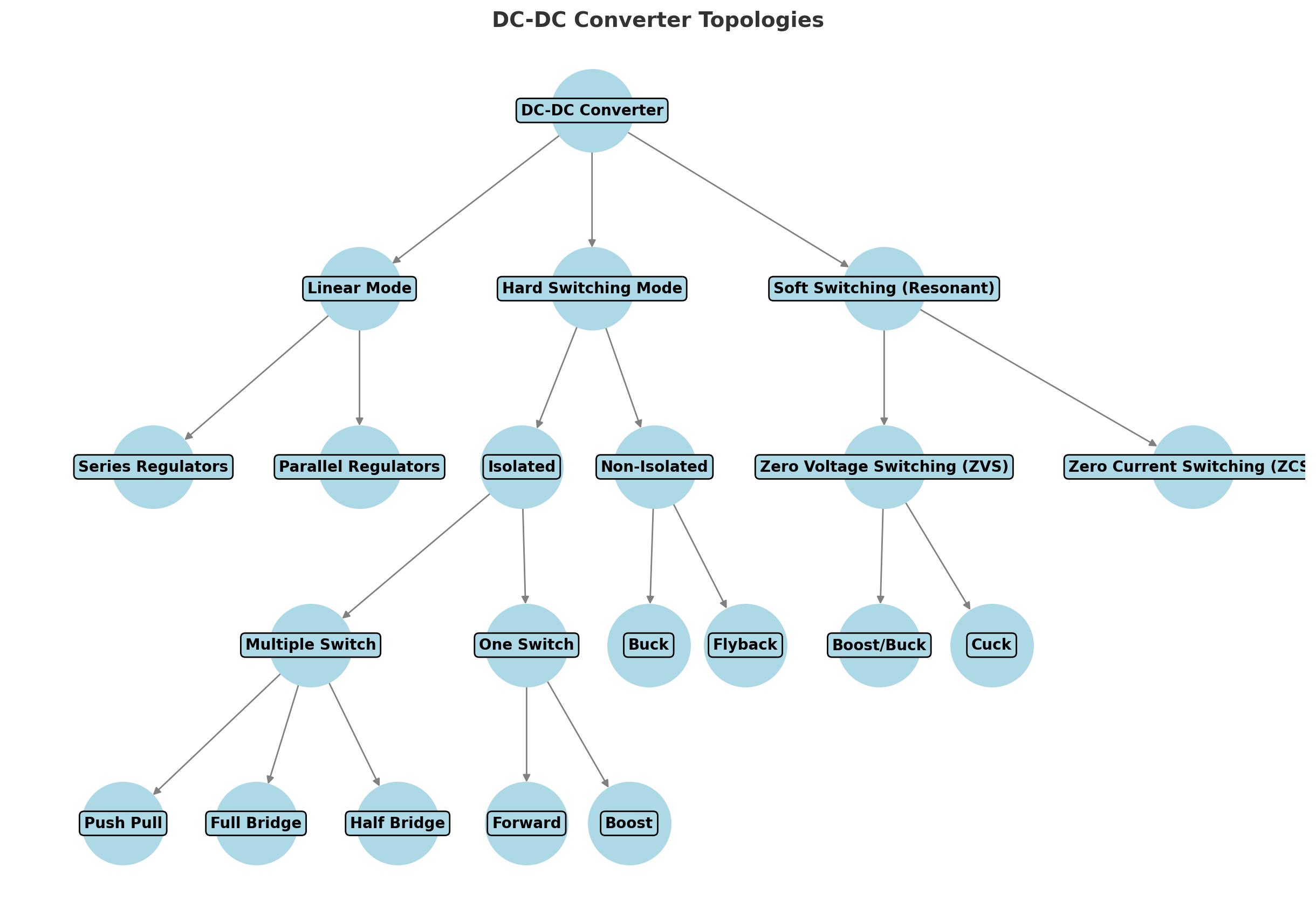
But among all these, the most popular DC-DC converters are these:
- Buck Converter (Step-down) – Converts a higher input voltage to a lower output voltage.
- Boost Converter (Step-up) – Converts a lower input voltage to a higher output voltage.
- Buck-Boost Converter – Can both increase and decrease voltage.
- Flyback Converter – Isolated topology used in low-power applications.
- Forward Converter – Used for higher power applications with transformer isolation.
- Push-Pull, Half-Bridge, and Full-Bridge – Advanced topologies for high-power applications.
Due to their efficiency and reliability, a Buck converter or a Full-Bridge topology is ideal for high-power applications (10V-72V input, 53V-60V output, 10A-40A).
2. Selecting Key Components:
Selecting the key component for an efficient DC-DC converter is very important. Because if the performance of each component is not aligned, your design will fail.
2.1 Choosing the Right MOSFETs
- Low Rds(on) MOSFETs reduce conduction losses.
- High-speed MOSFETs minimize switching losses.
- Example: Infineon OptiMOS or Vishay SiR series.
2.2 Inductor Selection
- Choose a low-core loss ferrite inductor.
- Inductor value is determined by: L=Vout(1−D)ΔILfswL = \frac{V_{out} (1 – D)}{\Delta I_{L} f_{sw}}
- Example: Würth Elektronik high-current inductors.
2.3 Capacitors
- Low ESR capacitors reduce ripple.
- Ceramic capacitors for high-frequency filtering.
- Example: Murata or Panasonic Polymer Electrolytics.
2.4 Diodes (for Non-Synchronous Converters)
- Schottky diodes minimize voltage drop.
- Example: STMicroelectronics STPS series.
2.5 Switching Controller
- Synchronous controllers improve efficiency.
- Example: Texas Instruments LM5176 or Analog Devices LT8705.
3. Circuit Design & Simulation:
To make the design perfect, you must simulate the design before implementation. Because, if you don’t simulate and make the hardware directly while you are not 100% confirm about the design, you may waste some money and time.
3.1 Designing the Control Loop
- Use feedback compensation to ensure stability.
- Type III compensation for high-performance applications.
- Simulation tools: LTspice, PSpice, or Simulink.
3.2 Power Stage Design
- Use proper gate drivers for MOSFETs.
- Implement soft switching techniques (ZVS/ZCS) for better efficiency.
3.3 Thermal Considerations
- Use heat sinks or thermal vias in the PCB.
- Consider active cooling (fans) for high-current applications.
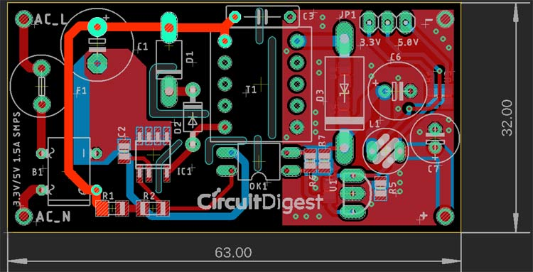
4. PCB Layout Best Practices:
There are some vital points for PCB designing of the DC-DC converter.
4.1 Minimize Parasitic Effects
- Short traces for high-current paths.
- Kelvin connections for accurate current sensing.
- Wide copper traces or planes to reduce resistance.
4.2 Grounding & Shielding
- Use a single-point ground for power and control.
- Separate high-power and low-power grounds.
4.3 EMI & Noise Reduction
- Snubber circuits across MOSFETs.
- Shielding around sensitive analog components.
5. Efficiency Optimization Techniques:
5.1 Reducing Switching Losses
- Use soft-switching techniques like Zero-Voltage Switching (ZVS) or Zero-Current Switching (ZCS).
- Lower switching frequency to reduce losses.
5.2 Reducing Conduction Losses
- Use low-Rds(on) MOSFETs.
- Optimize PCB trace thickness for current handling.
5.3 Improving Thermal Management
- Use heat sinks, fans, or liquid cooling in extreme cases.
- Thermal vias under MOSFETs and diodes.
6. Example Design: 48V to 56V, 20A Buck Converter:
Specifications:
- Input Voltage: 48V
- Output Voltage: 56V
- Output Current: 20A
- Efficiency Target: 95%+
- Switching Frequency: 100kHz
Component Selection:
| Component | Part Number | Notes |
|---|---|---|
| Controller | TI LM5176 | Synchronous Buck-Boost |
| MOSFETs | Infineon BSC010N04LS | Low Rds(on) for minimal losses |
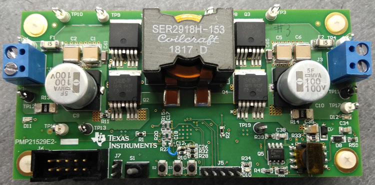
| Inductor | Coilcraft SER2918 | High-saturation current |
| Capacitors | Murata MLCC & Panasonic Polymer | Low ESR, high ripple current |
| Diodes | STMicro STPS30170 | Schottky for low loss |
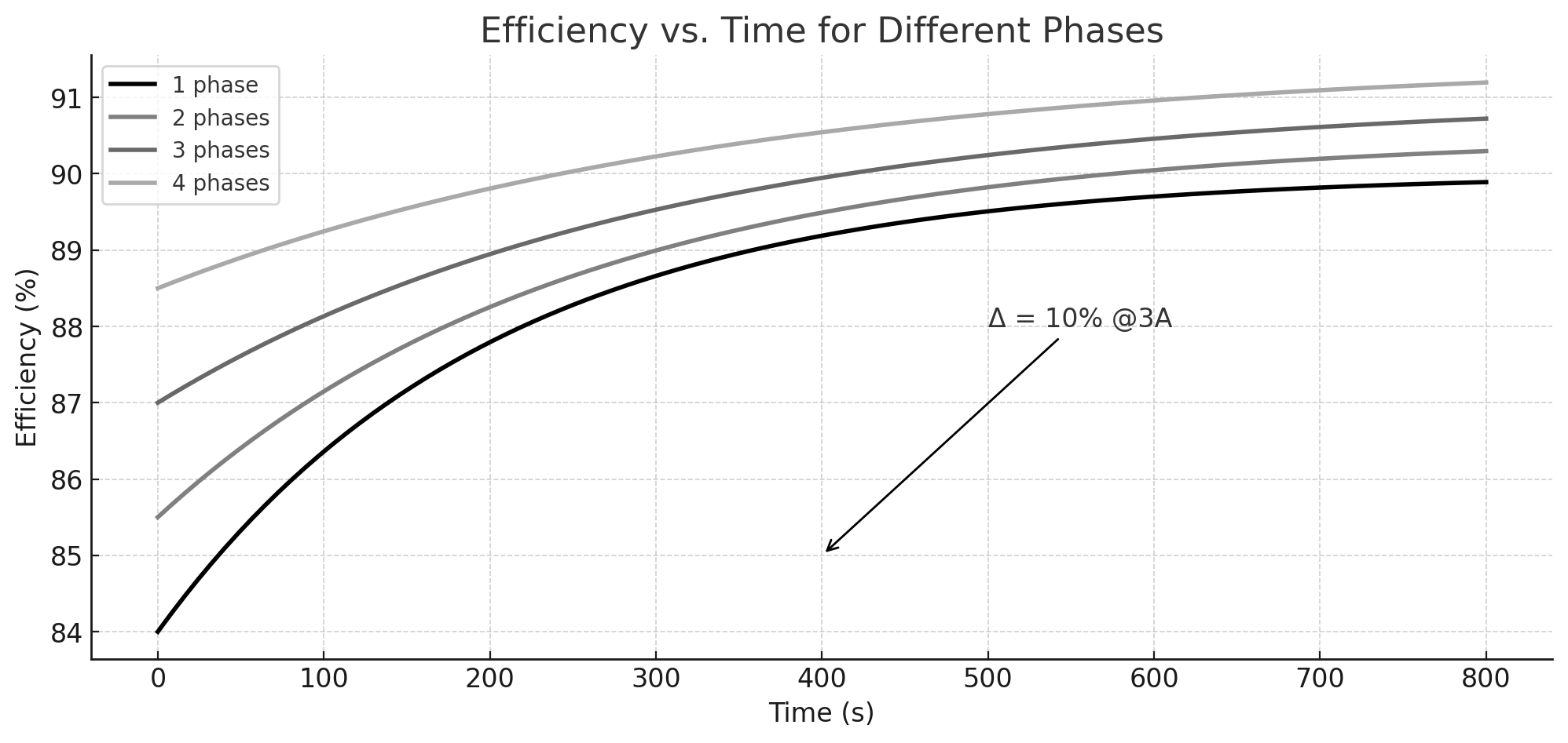
Efficiency Analysis:
- Simulated peak efficiency: ~96% at 50% load.
- Losses mainly due to switching and conduction losses.
- Improved by better thermal management & snubber design.
You can read: Step-by-Step Guide to Building an MPPT Controller with Arduino and a Synchronous Buck Converter
Conclusion:
Designing a high-efficiency DC-DC converter requires careful selection of topology, components, and PCB layout. By following the techniques outlined in this guide, you can optimize efficiency, thermal performance, and reliability for your specific application.
For a real-world implementation, use LTspice simulations, prototype testing, and thermal analysis tools to refine your design.
Additional Resources
- Texas Instruments Power Design Seminars
- Analog Devices LTspice Tutorials
- IEEE Papers on High-Efficiency Power Electronics
Do you need assistance with a specific design or simulation? Feel free to ask in the comments! 🚀
Liked this article? Subscribe to our newsletter:
or,
Visit LabProjectsBD.com for more inspiring projects and tutorials.
Thank you!


0 Comments