Learn how to create a digital clock with an ST7567 graphical LCD module and a DS3231 RTC module using an Arduino board. Follow the step-by-step guide and write the code to display the time and date readings from the RTC module on the ST7567 display.
⚠️Disclaimer:
Working with electricity involves serious risk. Ensure you have the necessary skills and take proper safety precautions before attempting any electrical projects. Proceed at your own risk — the author assumes no responsibility for any damage, injury, or issues resulting from the use or misuse of the information provided.
All content on this website is original and protected by copyright. Please do not copy or reproduce content without permission. While most of the resources shared here are open-source and freely accessible for your learning and benefit, your respect for our intellectual effort is appreciated.
If you find our tutorials helpful, consider supporting us by purchasing related materials or sharing our work — it helps keep the content flowing.
Need help or have questions? Leave a comment below — the author is always happy to assist!
Table of Contents
What is needed to make a clock?
To make a digital clock, you need a RTC for a real-time clock source, a display, and a microcontroller to manage these two basic devices. And some associative components such as buttons, LEDs, alarms, etc. But to know the basics, you need to know about the display and the RTC. Then you can add the other peripherals.
About ST7567 Display:
The ST7567 is a monochrome graphic LCD controller manufactured by Sitronix Technology Corporation. It is commonly used to drive small to medium-sized graphic displays that require high-resolution graphics and low power consumption.
The ST7567 controller supports a variety of display modes, including a static display mode, a scrolling display mode, and a partial display mode. It can handle up to 128×64 or 132×64 dot matrix displays, and it supports a wide range of display types, including STN, FSTN, and FFSTN.
In addition, the ST7567 controller has built-in features that make it easy to implement advanced graphics capabilities, such as multiple grayscale levels, pixel inversion, and an on-chip programmable contrast control circuit. It also has a built-in temperature compensation circuit to ensure stable display performance over a wide range of operating temperatures.
Overall, the ST7567 controller is a popular choice for many embedded systems and consumer electronics applications that require high-quality, low-power graphics displays.
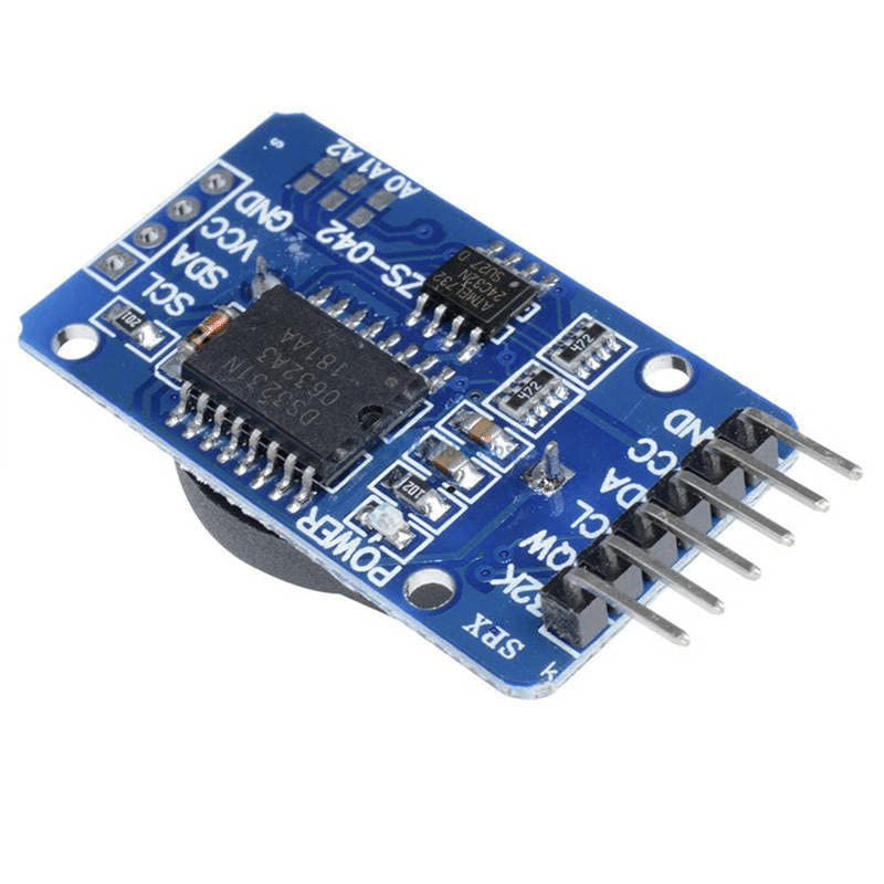
About DS3231:
The DS3231 is a low-cost, extremely accurate, and highly integrated Real Time Clock (RTC) module manufactured by Maxim Integrated Products. It is commonly used to provide timing and date-keeping functionality to a wide variety of electronic devices and systems, including microcontrollers, embedded systems, and consumer electronics.
The DS3231 module features a highly accurate temperature-compensated crystal oscillator (TCXO) that can maintain timekeeping accuracy within ±2ppm over a temperature range of -40°C to +85°C. It also has a built-in battery backup system that can keep the module powered for years in the absence of external power.
One of the notable features of the DS3231 module is its I2C interface, which makes it easy to integrate into a wide range of electronic systems. The module also has several built-in alarms and programmable timekeeping functions, such as 12 or 24-hour formats, and the ability to output signals at precise intervals.
Overall, the DS3231 is a highly reliable and accurate RTC module that is well-suited for a wide range of applications that require precise timekeeping and date-keeping capabilities.
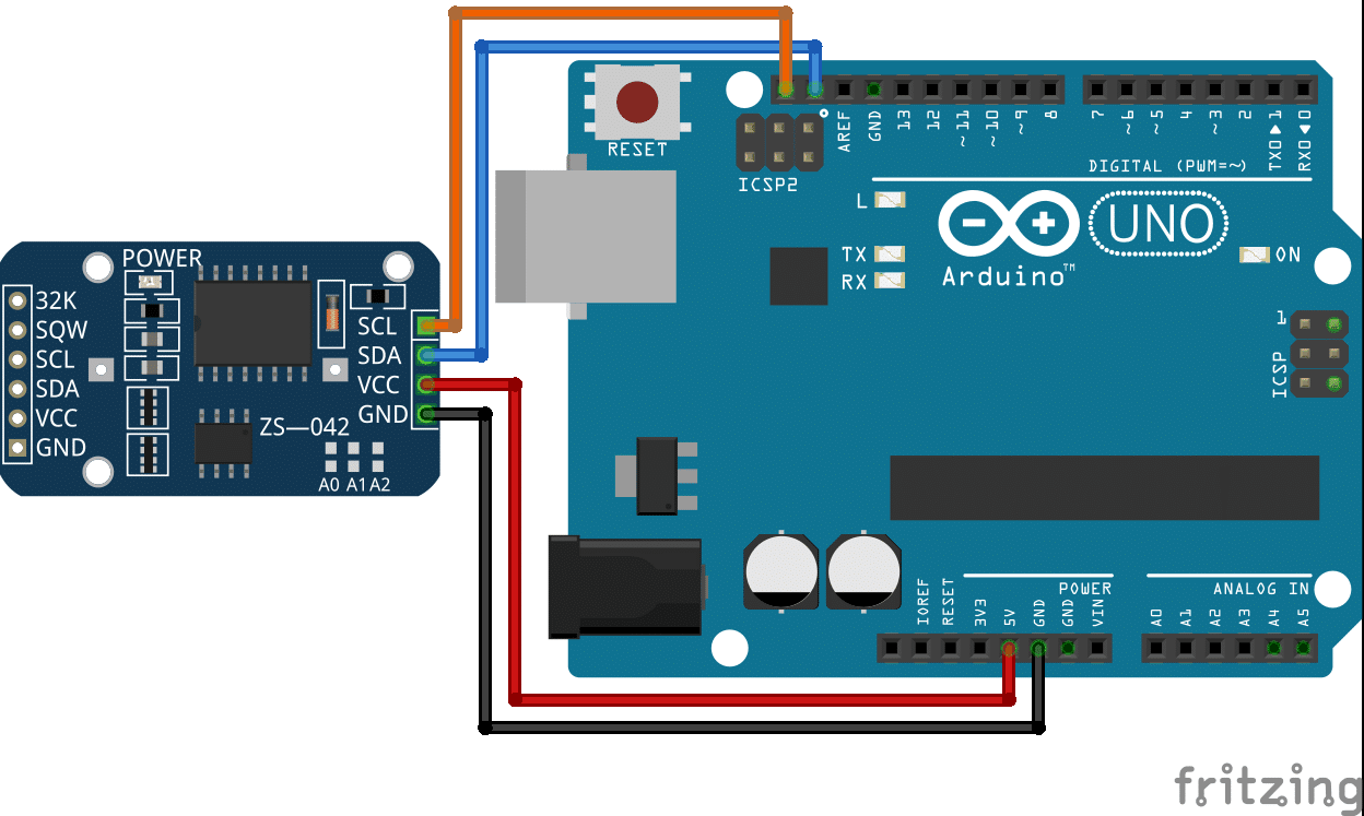
Interfacing DS3231 with Arduino:
To interface DS3231, you need to connect the RTC with Arduino through SCL & SDA pins. If you are using a DS3231 RTC module then no need to use pull-up resistors. But if you the IC directly use pull-up resistors (4K7).
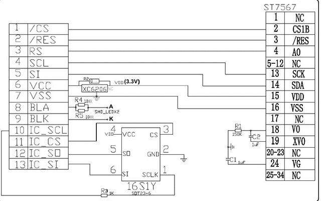
Interfacing ST7567 with Arduino:
I’ve published an article on this already. You can read it from the home page.
The diagram you need to follow:
Making a digital Clock:
After interfacing RTC and display, now you need to code for them. You can follow the following code:
//display configuration
#define LCD_CS 53
#define LCD_DC 9 // RS_any pin
#define LCD_RST 10
#include "ST7567_FB.h"
#include <SPI.h>
ST7567_FB lcd(LCD_DC, LCD_RST, LCD_CS);
#include "fonts_all.h"
//RTC setup
#include <RTClib.h>
#include <Wire.h>
RTC_DS3231 rtc;
char t[32];
int minute1 = 0, hour1 = 0, second1 = 0;
char hour[3], minute[3], second[3], day[3], month[3], year[3];
void setup() {
lcd.init();
lcd.setRotation(2);
lcd.setContrast(10);
lcd.cls();
lcd.setFont(c64enh);
//lcd.printStr(2, 2, "Water ATM v3.1");
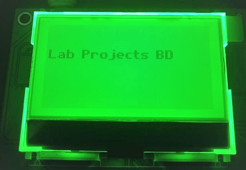
lcd.printStr(15, 10, "Lab Projects BD");
lcd.display();
Serial.begin(115200); //for Serial port to debug
Wire.begin();
rtc.begin();
rtc.adjust(DateTime(F(__DATE__), F(__TIME__)));
}
void loop() {
DateTime now = rtc.now();//read the time and sote in now
sprintf(hour, "%02d", now.hour());
sprintf(minute, "%02d", now.minute());
sprintf(second, "%02d", now.second());
sprintf(day, "%02d", now.day());
sprintf(month, "%02d", now.month());
sprintf(year, "%02d", now.year());
lcd.cls();
lcd.setFont(c64enh);
lcd.printStr(12, 10, "Lab Projects BD");
lcd.setFont(Term7x14PL);
lcd.printStr(2, 30, "Time:");
lcd.printStr(40, 30, hour);
lcd.printStr(58, 30, ":");
lcd.printStr(62, 30, minute);
lcd.printStr(77, 30, ":");
lcd.printStr(83, 30, second);
lcd.printStr(2, 50, "Date:");
lcd.printStr(40, 50, day);
lcd.printStr(57, 50, "-");
lcd.printStr(65, 50, month);
lcd.printStr(75, 50, "-");
lcd.printStr(85, 50, year);
lcd.display();
delay(500);
}
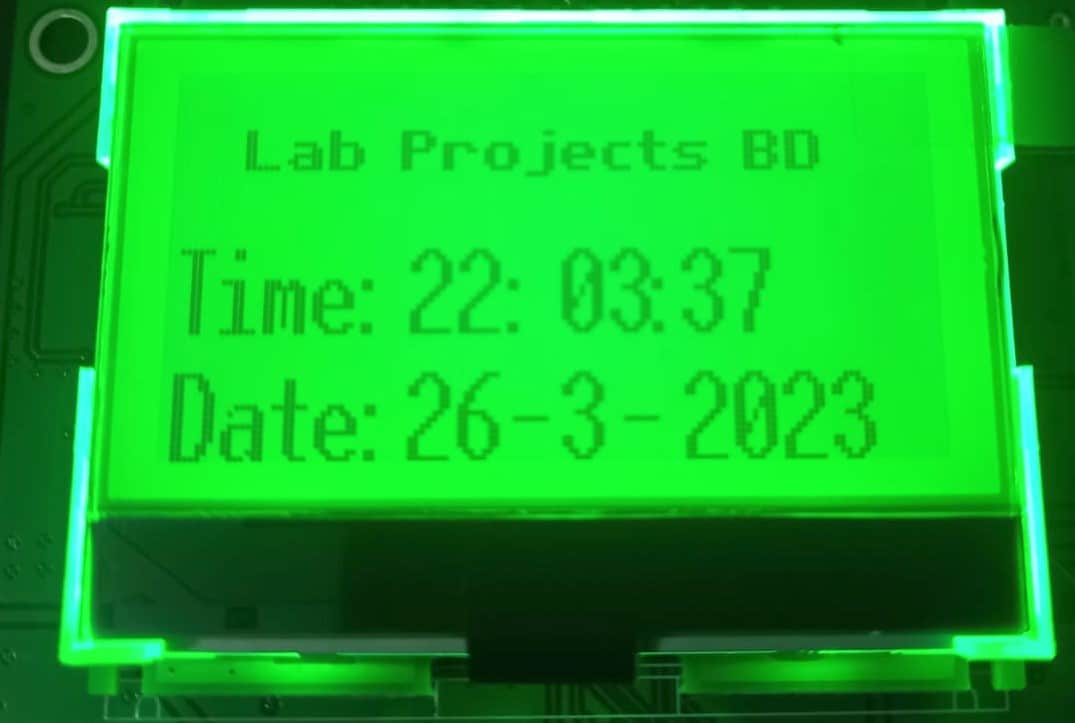
Result:
If your connections are ok, you will find this on the display:
Video:
Conclusion:
I hope this will help you making your own digital clock with Graphics. Happy coding….
Read more on:
- GLCD 128×64 ST7920 interfacing with STM32
- How to interface a 16×2 LCD with an STM32
- How to interface an OLED display with an STM32
- How to interface a 7-segment display with STM32
- How to interface ds3231 with STM32
Liked this article? Subscribe to our newsletter:
or,
Visit LabProjectsBD.com for more inspiring projects and tutorials.
Thank you!


0 Comments