A DC voltmeter can be used in many devices, even sometimes it becomes a must having feature for a device. In this article, we will learn how to make a DC voltmeter with Seven Segment and PIC micro-controller. So let’s make our DC voltmeter using PIC16F73 and mikroC coding.
⚠️Disclaimer:
Working with electricity involves serious risk. Ensure you have the necessary skills and take proper safety precautions before attempting any electrical projects. Proceed at your own risk — the author assumes no responsibility for any damage, injury, or issues resulting from the use or misuse of the information provided.
All content on this website is original and protected by copyright. Please do not copy or reproduce content without permission. While most of the resources shared here are open-source and freely accessible for your learning and benefit, your respect for our intellectual effort is appreciated.
If you find our tutorials helpful, consider supporting us by purchasing related materials or sharing our work — it helps keep the content flowing.
Need help or have questions? Leave a comment below — the author is always happy to assist!
Table of Contents
What is voltmeter?
A voltmeter is a measuring instrument that measures the voltage difference of two points of a circuit. It can be an analog or a digital one. But it doesn’t matter if it is analog or digital each one works in the same way, it measures voltage.
Voltage sensor
For voltage sensing simple resistor voltage divider works fine. All you need to maintain a suitable ratio and good noise filtering.
1K resistor 
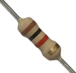
10K resistor 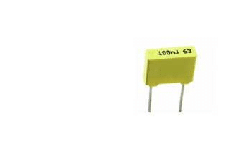
100n Capacitor
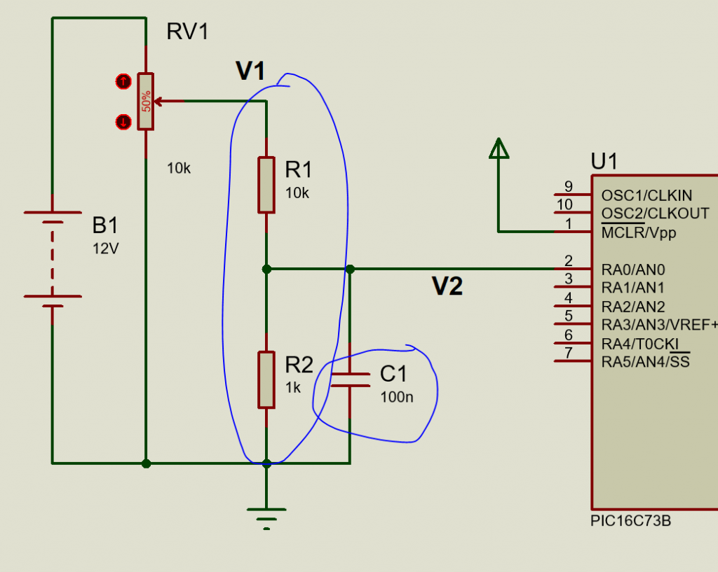
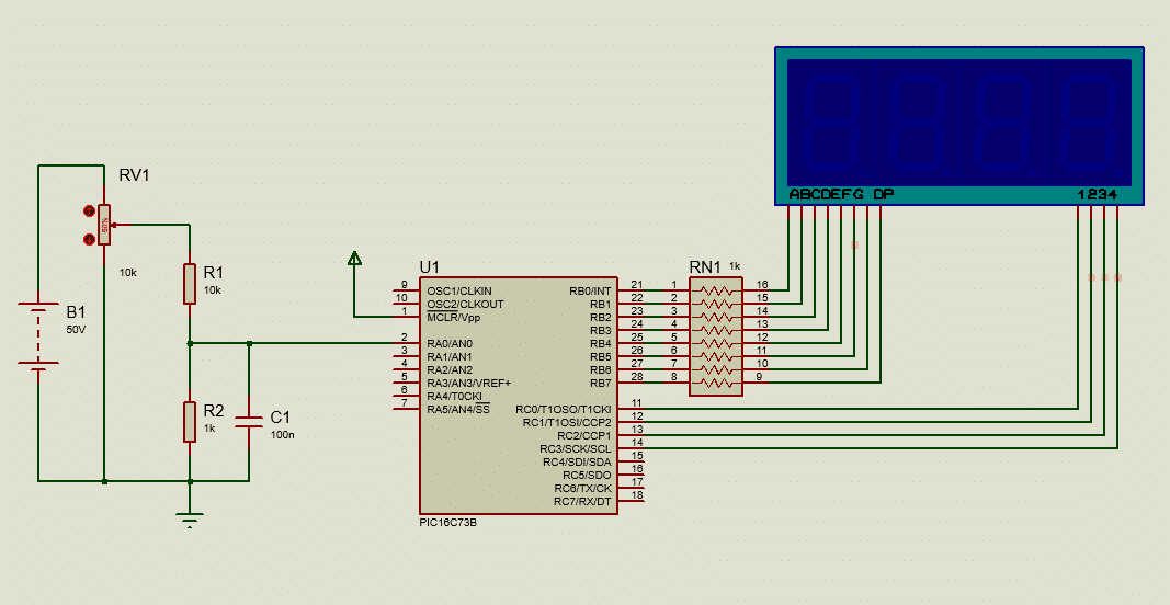
As you can see, R1 and R2 are forming a voltage divider and C1 is our noise filter. By calculating the resistor voltage divider rules, we can easily find the source voltage reading of B1.
For testing, we can use a POT-VR to measure different voltages.
Equations for voltage calculation:
To make the DC voltmeter using PIC16F73, we need to solve some calculations first. Here, we are using the PIC16F73 microcontroller. The ADC of this MCU is 8bit. That means, it measures voltage 0-5V and gives us a value 0-2^8 = 255 in correspond to the input voltage.
So the voltage at the pin of the MCU will be:
V2 = (5/255)*ADC_reading. Volt
From the resistor voltage divider rule, we can find the reading of V1.
V2 = V1 x R2/(R1+R2);
If we replace V2,
V1 = (R1+R2)/R2 x (5/255) x ADC_reading.
If you check carefully, we have some fixed values. R1, R2, 5 & 255 all are fixed in this equation. Only ADC_reading is variable.
That means,
V1 = (10K + 1K)/1K x 5/255 x ADC_reading.
=> V1 = 0.2157 x ADC_reading.
Now, we can easily find the supply voltage from the ADC reading value. Thus a DC voltmeter senses the input voltage.
Adding some additional feature:
As far we saw, a voltmeter can detect input voltage from ADC reading. But to make it more accurate, we can do some additional features.
If we take n number of samples and find the average value of them, our reading will be more accurate. More the value of ‘n’ more the accurate the value is.
Vavg = (V1 + V2 + … Vn)/n;
Now we need to make the circuit first for our voltmeter, then we’ll add the coding.
Circuit diagram:
Coding:
/*******************************************************************************
* Program for, "Seven Segment based DC voltmeter"                              *
* Program written by_ Engr. Mithun K. Das                                      *
* MCU:PIC16F73; Xtal:8MHz; mikroC pro for PIC v7.6.0                           *
* Date: 03-04-2020                                                             *
*******************************************************************************/


// array for segment digits, 0-9; CC;
char segment_array[]={0x3F,0x06,0x5B,0x4F,0x66,0x6D,0x7D,0x07,0x7F,0x6F};//CC_non dot

//pin declearation for digits
sbit digit0 at RC0_bit;
sbit digit1 at RC1_bit;
sbit digit2 at RC2_bit;
sbit digit3 at RC3_bit;

char digits[5];
void display_7segment(int number)
{
   digits[3]=number/1000u;      //store 1000th digit
   digits[2]=(number/100u)%10u; //store 100th digit
   digits[1]=(number/10u)%10u;  //store 10th digit
   digits[0]=(number/1u)%10u;   //store 1st digit
}

void InitTimer0()    //intterupt for 5ms timer ISR
{
  OPTION_REG     = 0x85;
  TMR0           = 100;
  INTCON         = 0xA0;
}

int position=0;
void Interrupt() iv 0x0004 ics ICS_AUTO
{
  if (TMR0IF_bit)
  {
    TMR0IF_bit   = 0;
    TMR0         = 100;

    digit0 = 1;
    digit1 = 1;
    digit2 = 1;
    digit3 = 1;
    if(position>3)position=0;

    PORTB = segment_array[digits[position]];
    if(position==3)
    {
        digit0 = 0;
        digit1 = 1;
        digit2 = 1;
        digit3 = 1;
    }
    else if(position==2)
    {
        digit0 = 1;
        digit1 = 0;
        digit2 = 1;
        digit3 = 1;
    }
    else if(position==1)
    {
        digit0 = 1;
        digit1 = 1;
        digit2 = 0;
        digit3 = 1;
    }
    else if(position==0)
    {
        digit0 = 1;
        digit1 = 1;
        digit2 = 1;
        digit3 = 0;
    }
    position++;
  }
}


unsigned int adc_value=0;
void main()
{
 TRISA=0xFF;//all input
 TRISB=0x00;//all output
 TRISC=0x00;//all output
 PORTB=0x00;
 PORTC=0x00;//clear ports
 ADCON1=0x00;
 ADCON0=0x01;//AN0 selected
 InitTimer0();//5ms timer
 while(1)
 {

    adc_value = ADC_Read(0)*0.21568;//read adc value
    display_7segment(adc_value); //print in display

 }
}// end
Here we have done the coding for our voltmeter. Now we need to check the result if it can detect the input voltage properly.
Result 1:

As you see, it can detect the maximum reading. Here, we set B1 as 50V, and our voltmeter detected and displayed that 50V. But, to measure the fractions, we have to modify our code a little bit.
If we multiply the reading by 100 and add a dot (.) just after the second digit then we can make a more decent voltmeter.
To do that, we have to add some tricks.
if(position==2) PORTB = segment_array[digits[position]]+128;
else PORTB = segment_array[digits[position]];
If we add this code in ISR, it will show a dot point in position 2 like this:
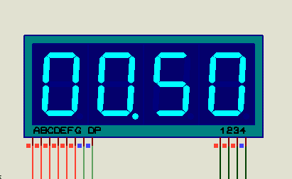
Then just after multiplying by 100 while taking reading:

Now, we can add our additional features. The average reading…
    adc_value=0;//clear pervious value
    for(k=0;k<10;k++)
    {
      adc_value += ADC_Read(0)*21.568;//read adc value
    }
    adc_value/=10;
Here, we must clear the previous value of adc_value, otherwise, it will keep adding the voltage reading. And keeping the multiplication inside for loop makes it more accurate.
Final Code:
So the final code is now this:
/*******************************************************************************
* Program for, "Seven Segment based DC voltmeter"                              *
* Program written by_ Engr. Mithun K. Das                                      *
* MCU:PIC16F73; Xtal:8MHz; mikroC pro for PIC v7.6.0                           *
* Date: 03-04-2020                                                             *
*******************************************************************************/


// array for segment digits, 0-9; CC;
char segment_array[]={0x3F,0x06,0x5B,0x4F,0x66,0x6D,0x7D,0x07,0x7F,0x6F};//CC_non dot

//pin declearation for digits
sbit digit0 at RC0_bit;
sbit digit1 at RC1_bit;
sbit digit2 at RC2_bit;
sbit digit3 at RC3_bit;

char digits[5];
void display_7segment(int number)
{
   digits[3]=number/1000u;      //store 1000th digit
   digits[2]=(number/100u)%10u; //store 100th digit
   digits[1]=(number/10u)%10u;  //store 10th digit
   digits[0]=(number/1u)%10u;   //store 1st digit
}

void InitTimer0()    //intterupt for 5ms timer ISR
{
  OPTION_REG     = 0x85;
  TMR0           = 100;
  INTCON         = 0xA0;
}

int position=0;
void Interrupt() iv 0x0004 ics ICS_AUTO
{
  if (TMR0IF_bit)
  {
    TMR0IF_bit   = 0;
    TMR0         = 100;

    digit0 = 1;
    digit1 = 1;
    digit2 = 1;
    digit3 = 1;
    if(position>3)position=0;
    if(position==2) PORTB = segment_array[digits[position]]+128;
    else PORTB = segment_array[digits[position]];
    if(position==3)
    {
        digit0 = 0;
        digit1 = 1;
        digit2 = 1;
        digit3 = 1;
    }
    else if(position==2)
    {
        digit0 = 1;
        digit1 = 0;
        digit2 = 1;
        digit3 = 1;
    }
    else if(position==1)
    {
        digit0 = 1;
        digit1 = 1;
        digit2 = 0;
        digit3 = 1;
    }
    else if(position==0)
    {
        digit0 = 1;
        digit1 = 1;
        digit2 = 1;
        digit3 = 0;
    }
    position++;
  }
}


unsigned int adc_value=0;
int k=0;
void main()
{
 TRISA=0xFF;//all input
 TRISB=0x00;//all output
 TRISC=0x00;//all output
 PORTB=0x00;
 PORTC=0x00;//clear ports
 ADCON1=0x00;
 ADCON0=0x01;//AN0 selected
 InitTimer0();//5ms timer
 while(1)
 {

    adc_value=0;//clear pervious value
    for(k=0;k<10;k++)
    {
      adc_value += ADC_Read(0)*21.568;//read adc value
    }
    adc_value/=10;

    display_7segment(adc_value); //print in display

 }
}
//
You can check the AC voltmeter with PIC16F73 too. & AC panel meter with capacitor power supply.
Final Result:
Now our DC voltmeter using PIC16F73 is ready to test. Here is the test result in simulation:
Now, you have got everything to make a DC voltmeter. Although there is a little mismatch (less than 2%) this mismatch can be eliminated. For this, you need to use high accurate resistors.
I hope you enjoyed the project and will be able to make one for yourself. If you need any help, I’m here. Thanks. Enjoy!
Liked this article? Subscribe to our newsletter:
or,
Visit LabProjectsBD.com for more inspiring projects and tutorials.
Thank you!
Check this out: 5 coolest multimeters you can buy


8 Comments
Rezaul · 08/08/2020 at 6:52 am
How can I use pic 16f676 in CA led?
Mithun K. Das · 08/08/2020 at 7:33 am
Yes. Just configure the code for CA.
Rezaul · 10/08/2020 at 7:36 am
Pin configuration not same!
Mithun K. Das · 10/08/2020 at 9:13 am
Yes, signal should be changed for CA. You need to configure the code for CA display. While CC works in 1>>0 configuration, CA will work in 0<<1 configuration.
Joy · 28/11/2020 at 7:50 am
How I can use Ameter and Volt meter in one pic16f73 with one seven seg display.
Two in one output.Amp/Voltmeter DC.
Mithun K. Das · 28/11/2020 at 12:20 pm
By time-shifting you can display either voltage or current data on display. Like voltage is displayed for 3 seconds, then current for 3 seconds. And calculate voltage and current by the same time shifting.
Joy · 28/11/2020 at 8:28 am
How can I make a Amp and Voltmeter pic16f73 in one Senensegment Display. Two input one output.
Dc Volt/Amper meter..
Mithun K. Das · 28/11/2020 at 12:20 pm
By time-shifting you can display either voltage or current data on display. Like voltage is displayed for 3 seconds, then current for 3 seconds. And calculate voltage and current by the same time shifting.