Like the high voltage AC meter, we can use the same Op-Amp circuit to measure high voltage DC voltmeter. In this article, we are going to learn how to make a high voltage DC voltmeter using a micro-controller and Op-Amp circuitry.
⚠️Disclaimer:
Working with electricity involves serious risk. Ensure you have the necessary skills and take proper safety precautions before attempting any electrical projects. Proceed at your own risk — the author assumes no responsibility for any damage, injury, or issues resulting from the use or misuse of the information provided.
All content on this website is original and protected by copyright. Please do not copy or reproduce content without permission. While most of the resources shared here are open-source and freely accessible for your learning and benefit, your respect for our intellectual effort is appreciated.
If you find our tutorials helpful, consider supporting us by purchasing related materials or sharing our work — it helps keep the content flowing.
Need help or have questions? Leave a comment below — the author is always happy to assist!
Table of Contents
How to sense high voltage floating DC with Op-Amp?
Like the Op-Amp circuit of AC voltage sensing, we can use this same circuit to sense high voltage DC. Here only one change we need to do is, the reference voltage will be 0V. Here is the modified sensing circuit.

In this circuit, the input is floating. That means, it is not connected to the GND or VCC of the measuring circuit. This way, decent isolation is possible. Here, the gain of this circuit will be:
Gain = R9/(R2+R6+R7+R8)
Input range can be increased by selecting suitable resistors. If the input voltage is higher than 1KV, use more resistors rather than selecting higher resistances. Using more resistors in series provide good heat dissipation as well as good isolation.
Circuit diagram of high voltage DC voltmeter:
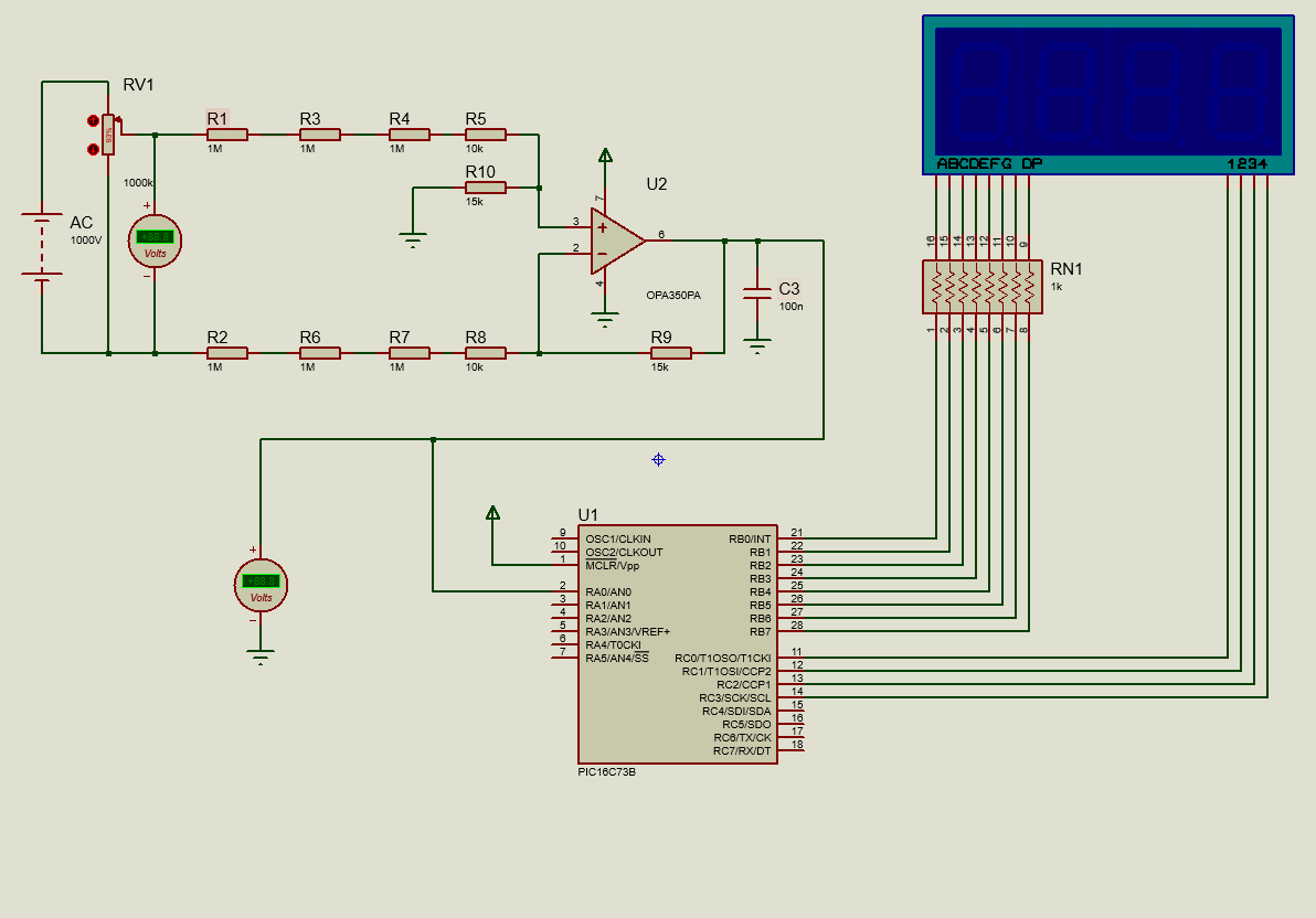
As in the circuit diagram of the AC voltmeter, the Op-Amp circuit is converting the high voltage into a low voltage range. Then the ADC of the micro-controller is calculating the input voltage.
Coding:
/*******************************************************************************
* Program for "High voltage DC voltmeter"                                      *
* Program written by_ Engr. Mithun K. Das                                      *
* MCU:PIC16F73; X-Tal:8MHz; mikroC pro for PIC v7.6.0                          *
* Date:05-05-2020                                                              *
*******************************************************************************/
char segment_array[]={0x3F,0x06,0x5B,0x4F,0x66,0x6D,0x7D,0x07,0x7F,0x6F};//cmmon cathode_non dot

sbit digit0 at RC0_bit;
sbit digit1 at RC1_bit;
sbit digit2 at RC2_bit;
sbit digit3 at RC3_bit;

char digits[5];
void display_7segment(int number)
{
   digits[3]=number/1000u;
   digits[2]=(number/100u)%10u;
   digits[1]=(number/10u)%10u;
   digits[0]=(number/1u)%10u;
}

void InitTimer0()
{
  OPTION_REG     = 0x85;
  TMR0           = 100;
  INTCON         = 0xA0;
}

int position=0;
void Interrupt() iv 0x0004 ics ICS_AUTO
{
  if (TMR0IF_bit)
  {
    TMR0IF_bit   = 0;
    TMR0         = 100;

    digit0 = 1;
    digit1 = 1;
    digit2 = 1;
    digit3 = 1;
    if(position>3)position=0;

    if(position==1)PORTB = segment_array[digits[position]]+128; //dot point
    else PORTB = segment_array[digits[position]];

    if(position==3)
    {
        digit0 = 0;
        digit1 = 1;
        digit2 = 1;
        digit3 = 1;
    }
    else if(position==2)
    {
        digit0 = 1;
        digit1 = 0;
        digit2 = 1;
        digit3 = 1;
    }
    else if(position==1)
    {
        digit0 = 1;
        digit1 = 1;
        digit2 = 0;
        digit3 = 1;
    }
    else if(position==0)
    {
        digit0 = 1;
        digit1 = 1;
        digit2 = 1;
        digit3 = 0;
    }
    position++;
  }
}


unsigned long adc_rd0=0,dc_voltage;
int k=0;
void main()
{
 TRISA=0xFF;//all in
 TRISB=0x00;//all output
 TRISC=0x00;//all output
 PORTB=0x00;
 PORTC=0x00;//clear ports
 ADCON1=0x00;//all analog in
 InitTimer0();//5ms timer
 while(1)
 {
      ADCON0 = 0b00000001;//select AN0
      adc_rd0 = 0;//clear data
      for(k=0;k<10;k++)
      {
         adc_rd0+=ADC_Read(0)*39.2;
         Delay_ms(10);
      }
      adc_rd0/=10;
      dc_voltage = adc_rd0;

      display_7segment(dc_voltage);
 }
}//
Here we are calculating the input high voltage with this function where an average of 10 samples is calculated. 39.2 is our calibration factor. Further calibration may be required with a practical circuit as resistances has a tolerance.
ADCON0 = 0b00000001;//select AN0
adc_rd0 = 0;//clear data
for(k=0;k<10;k++)
{
adc_rd0+=ADC_Read(0)*39.2;
Delay_ms(10);
}
adc_rd0/=10;
dc_voltage = adc_rd0;
Testing result:
Here is the proteus testing result.
I personally implemented this type of circuit in some commercial devices. The circuit worked fine for me. I hope, you can make one for yourself too.
In this project, you learned how to measure floating high voltage DC. Here, we tested 1000V only. But if you select the resistors carefully, you can measure more than 2500V with this circuit.
Remember, electricity is always dangerous. Work carefully at your own risk!!!
Hope you enjoyed the project. If you need any help, I’m here. Just ask. Thank you, Enjoy!
Liked this article? Subscribe to our newsletter:
or,
Visit LabProjectsBD.com for more inspiring projects and tutorials.
Thank you!
Check this out: 5 coolest multimeters you can buy


5 Comments
JatinderBir Singh · 11/10/2021 at 12:02 pm
When I try to compile below line gives error
adc_rd0+=ADC_Read(0)*39.2;
MKDas · 14/10/2021 at 11:36 am
Mark the ADC library from the library manager.
JatinderBir Singh · 19/10/2021 at 2:16 pm
Thanks
pinki · 14/11/2022 at 3:33 am
adc_rd0+=ADC_Read(0)*39.2; error
89 324 Undeclared identifier ‘ADC_Read’ in expression MyProject.c
in library manager
ADC_Read
Prototype unsigned ADC_Read(unsigned short channel);
Returns 8, 10 or 12-bit unsigned value read from the specified channel (MCU dependent).
Description Initializes PIC’s internal ADC module to work with RC clock. Clock determines the time period necessary for performing AD conversion (min 12TAD).
Parameter channel represents the channel from which the analog value is to be acquired. Refer to the appropriate datasheet for channel-to-pin mapping.
Note : This function doesn’t work with the external voltage reference source, only with the internal voltage reference.
Requires The MCU with built-in ADC module.
Before using the function, be sure to configure the appropriate TRISx bits to designate pins as inputs.
Example unsigned tmp;
…
tmp = ADC_Read(2); // Read analog value from channel 2
write there
please help me
MKDas · 14/11/2022 at 11:55 am
Select ADC library first. then compile.