Sine wave generation using dsPIC is one of the most popular topics in electronics. Many engineers and hobbyists try this project. So in this article, I’ll start writing on sine wave generating using dsPIC.
⚠️Disclaimer:
Working with electricity involves serious risk. Ensure you have the necessary skills and take proper safety precautions before attempting any electrical projects. Proceed at your own risk — the author assumes no responsibility for any damage, injury, or issues resulting from the use or misuse of the information provided.
All content on this website is original and protected by copyright. Please do not copy or reproduce content without permission. While most of the resources shared here are open-source and freely accessible for your learning and benefit, your respect for our intellectual effort is appreciated.
If you find our tutorials helpful, consider supporting us by purchasing related materials or sharing our work — it helps keep the content flowing.
Need help or have questions? Leave a comment below — the author is always happy to assist!
Table of Contents
About dsPIC:
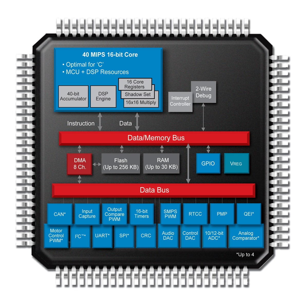
The dsPIC (digital signal controller) is a microcontroller family developed by Microchip Technology. They are designed to be used in a wide range of digital signal processing (DSP) applications, such as audio and video processing, motor control, and communications.
dsPICs have a powerful architecture that includes a digital signal processor (DSP) core and a microcontroller core. The DSP core is optimized for high-speed signal processing, with fast instruction execution and a wide range of DSP-specific instructions.
The microcontroller core, on the other hand, is designed for general-purpose control tasks, with a variety of peripheral modules and memory options.
Some of the key features of dsPICs include:
- High-performance DSP and microcontroller cores
- Wide range of peripheral modules, including PWM, ADC, UART, and SPI
- Large memory options, including flash memory and RAM
- Support for a wide range of communication interfaces, such as CAN, Ethernet, and USB
- High-speed processing, with clock, speeds up to 70 MHz
Overall, dsPICs are a powerful and flexible solution for a wide range of digital signal processing applications.
There are also similar alternatives, but of course, there are significant differences. So let’s compare it with other similar MCUs.
dsPIC vs PIC24:
Both dsPIC and PIC24 are microcontroller families developed by Microchip Technology, but they have some key differences.
The main difference between dsPIC and PIC24 is that dsPICs are designed for digital signal processing (DSP) applications, while PIC24s are designed for general-purpose control tasks.
dsPICs have a powerful architecture that includes a digital signal processor (DSP) core and a microcontroller core. The DSP core is optimized for high-speed signal processing, with fast instruction execution and a wide range of DSP-specific instructions.
The microcontroller core, on the other hand, is designed for general-purpose control tasks, with a variety of peripheral modules and memory options.
PIC24s, on the other hand, are general-purpose microcontrollers that are designed for a wide range of control and data acquisition applications. They have a wide range of peripheral modules, including PWM, ADC, UART, and SPI, and support for a wide range of communication interfaces, such as CAN, Ethernet, and USB.
dsPICs have a larger memory option, including flash memory and RAM, and also have high-speed processing, with clock speeds up to 70 MHz.
Overall, dsPICs are a good choice for digital signal processing applications that require high-speed processing and specialized DSP instructions, while PIC24s are a good choice for general-purpose control and data acquisition applications.
dsPIC vs STM:
dsPIC and STM are two different families of microcontrollers developed by different manufacturers, Microchip and STMicroelectronics respectively.
The dsPIC (digital signal controller) is a microcontroller family developed by Microchip Technology, designed to be used in a wide range of digital signal processing (DSP) applications, such as audio and video processing, motor control, and communications.
They have a powerful architecture that includes a digital signal processor (DSP) core and a microcontroller core.STM (STMicroelectronics) microcontrollers are widely used in a variety of applications including embedded systems, industrial automation, automotive, and consumer electronics. They offer a wide range of microcontroller families, such as STM32, STM8, and ST7, each with different performance, memory, and peripheral options.
STM32 microcontrollers are powerful and efficient Cortex-M-based microcontrollers with a wide range of peripherals and memory options. They have a high-performance 32-bit Arm Cortex-M core and DSP instruction set. They offer a wide range of peripherals including ADCs, timers, communication interfaces and advanced security features.

The key difference between dsPIC and STM is that dsPICs are specifically designed for digital signal processing (DSP) applications while STM microcontrollers are versatile and can be used in different applications including DSP, embedded systems, and industrial automation. STM microcontrollers have a powerful Cortex-M-based core while dsPICs have a specialized DSP core.
Overall, both dsPIC and STM microcontrollers are powerful solutions for different types of applications, and the choice between them will depend on the specific requirements of your project.
now, you can decide why dsPIC is more popular in signal generation type works.
Now, how to generate a sine wave using dsPIC?
To generate a sine wave using a dsPIC, you will need to use the microcontroller’s built-in pulse-width modulation (PWM) module. This module can be configured to output a signal with a specific frequency and duty cycle, which can be used to approximate a sine wave.
The first step is to configure the PWM module with the desired frequency and duty cycle. This can be done using the dsPIC’s built-in registers. Once configured, the PWM module can be enabled and the sine wave will be output on the designated pin.
Additionally, you can use the look-up table method to generate a sine wave. You can pre-calculate the sine value for the specific range of angles and store them in a table. You can then use the PWM module to output the sine wave by reading the table.
Another method is to use a sine wave generator IC and connect it with the dsPIC to get the sine wave output.
It is important to note that the quality of the generated sine wave will depend on the resolution of the PWM module and the size of the look-up table.
SPWM look-up table:
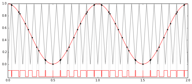
A SPWM (Sinusoidal Pulse Width Modulation) lookup table is a pre-calculated table of values that are used to generate a sinusoidal waveform for use in a SPWM signal. The SPWM signal is typically used in motor control applications and is generated by modulating the duty cycle of a rectangular waveform to produce a waveform that closely approximates a sine wave.
A lookup table is used to store the values of the sine wave, and these values are used to set the duty cycle of the rectangular waveform. The lookup table is typically stored in the microcontroller’s memory and can be accessed at high speeds to produce the SPWM signal.
The values in the lookup table are typically pre-calculated using a mathematical formula or by using a software tool. The size of the lookup table will depend on the resolution of the SPWM signal required. A larger lookup table will provide a higher resolution SPWM signal, but will also require more memory to store.
To generate the SPWM look-up table use this
In general, creating a lookup table for a SPWM signal is a simple process, but it requires accurate calculations to generate the sine wave values, and also it requires memory to store these values. In addition, the process of generating the SPWM signal using a lookup table requires high-speed access to the lookup table values to achieve the desired resolution.
Before using dsPIC to generate SWPM, you must understand some features of dsPIC.
What is PLL:
A PLL (Phase Locked Loop) is a circuit that is used to generate a stable, high-frequency clock signal from a lower-frequency input signal. PLLs are commonly used in a variety of applications, including frequency synthesis, clock generation and recovery, and signal modulation.
One of the main uses of PLLs is frequency synthesis, where a lower-frequency input signal is multiplied by a factor, known as the multiplication factor, to generate a higher-frequency output signal. This is typically used in applications such as radio frequency (RF) communications, where a stable, high-frequency carrier signal is required for modulation and demodulation of the data signal.
PLLs are also used in clock generation and recovery applications, where a stable, high-frequency clock signal is required for digital circuits. The PLL generates a clock signal that is locked to the frequency of an input signal, such as a crystal oscillator. This allows for the generation of a stable clock signal that is not affected by changes in temperature or voltage.
Another use of PLLs is in signal modulation, where the PLL is used to generate a modulated output signal from an input signal. This is commonly used in applications such as frequency modulation (FM) and phase modulation (PM).
Overall, PLLs are widely used in different applications, they help to generate stable, high-frequency signals, and also to modulate signals. They can be used in many different fields like communications, digital circuits, and control systems.
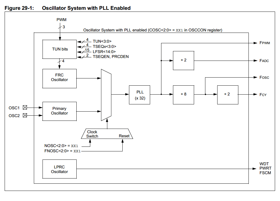
In short, PLL allows you to run the system by multiplying the system clock. This helps dsPIC processing its task much faster which we need.
Times of dsPIC:
dsPIC microcontrollers, like many other microcontrollers, have built-in timer modules that can be used to generate timed events and perform other timing-related tasks. The timers in dsPIC microcontrollers are typically used for tasks such as:
- Timekeeping: Keeping track of the time elapsed since the last reset or power-on, or measuring the time between two events.
- PWM generation: Generating PWM signals for motor control or other applications.
- Capture and compare: Measuring the time between two events, or comparing a timer value to a predefined value for triggering an event.
- Interrupt generation: Generating interrupts at timed intervals or when a specific event occurs.
- Real-time clock: Keeping track of the time and date, and providing a timebase for scheduling tasks.
The dsPIC microcontroller has several timers, each with its own set of features and capabilities. Some of the most commonly used timers in dsPIC microcontrollers include:
- Timer1: It’s a 16-bit timer/counter that can be used for timekeeping, PWM generation, and capture/compare operations.
- Timer2: It’s a 16-bit timer/counter that is similar to Timer1 but with a smaller instruction set.
- Timer3: It’s a 16-bit timer/counter that is similar to Timer1 but with a smaller instruction set.
- Timer4: It’s a 32-bit timer/counter that is similar to Timer1 but with a higher resolution.
- Timer5: It’s a 32-bit timer/counter that is similar to Timer4 but with a smaller instruction set.
Each timer has its own set of registers and control bits that can be configured to perform different tasks. The choice of which timer to use will depend on the specific requirements of your application and the resources available on the microcontroller.
PWM generation with dsPIC:
PWM (Pulse Width Modulation) is a technique used to generate a variable-duty-cycle signal that can be used to control the speed or position of motors or other devices. PWM can be generated using a timer module in the dsPIC microcontroller.
The basic steps for generating PWM with a dsPIC microcontroller are:
- Configure the timer module: The timer module is configured to operate in the PWM mode. This includes setting the period and the duty cycle of the PWM signal.
- Set the PWM output pin: The PWM output pin is set as an output and connected to the device that is being controlled.
- Start the timer: The timer is started to begin generating the PWM signal.
- Change the duty cycle: The duty cycle of the PWM signal can be changed by adjusting the value of the compare register in the timer module.
The specific steps for generating PWM with a dsPIC microcontroller will depend on the particular timer module being used and the device that is being controlled. For example, if you are using Timer2, you have to set the appropriate control registers and the right prescaler value.
It’s worth mentioning that, using a lookup table to generate the PWM signal is also a good option, it requires more memory but it will give you a more accurate signal.
In general, PWM generation with dsPIC microcontroller is a simple process that can be accomplished by configuring the timer module, setting the PWM output pin, and adjusting the duty cycle of the PWM signal as needed. The specific details of how to generate PWM with a dsPIC microcontroller will depend on the particular timer module and the device that is being controlled.
Example code to generate PWM using dsPIC:
Here is an example of code for generating PWM with a dsPIC microcontroller using the Timer2 module:
#include <p24Fxxxx.h>

// Configure Timer2 to generate PWM signal
void configurePWM() {
    T2CONbits.TON = 0; // Disable Timer2
    T2CONbits.TCS = 0; // Select internal instruction cycle clock
    T2CONbits.TGATE = 0; // Disable Gated Timer mode
    T2CONbits.TCKPS = 0b11; // Select 1:256 Prescaler
    PR2 = 249; // Set period register to 249
    T2CONbits.TON = 1; // Start Timer2
}

// Set duty cycle of PWM signal
void setDutyCycle(int dutyCycle) {
    if(dutyCycle < 0) dutyCycle = 0;
    if(dutyCycle > 100) dutyCycle = 100;
    dutyCycle = (dutyCycle * PR2) / 100;
    OC1RS = dutyCycle; // Set duty cycle register
}

int main() {
    configurePWM();
    setDutyCycle(50); // Set duty cycle to 50%

    while(1) {
        // Main program loop
    }
    return 0;
}
This code uses the Timer2 module to generate a PWM signal with a duty cycle of 50%. The period of the PWM signal is set to 249, and the prescaler is set to 1:256. The duty cycle can be changed by calling the setDutyCycle() function and passing in the desired duty cycle as a percentage.
It’s worth mentioning that, this is just an example, you may need to adjust the prescaler value and the period value based on your specific application requirements. Also, you need to check the pin out of your dsPIC microcontroller to know which pin is connected to the Timer2 module.
Also, you should keep in mind that, you need to include the correct header files for your device and the correct configuration bit settings for your device.
Now, you need a timer interrupt to control this PWM so that, you can carry the duty cycle and which will generate the SPWM finally.
Timer interrupt code example with dsPIC:
Here is an example of code for generating PWM with Timer2 and using Timer2 interrupt in dsPIC:
#include <p24Fxxxx.h>

int dutyCycle = 0;

// Configure Timer2 to generate PWM signal
void configurePWM() {
    T2CONbits.TON = 0; // Disable Timer2
    T2CONbits.TCS = 0; // Select internal instruction cycle clock
    T2CONbits.TGATE = 0; // Disable Gated Timer mode
    T2CONbits.TCKPS = 0b11; // Select 1:256 Prescaler
    PR2 = 249; // Set period register to 249
    TMR2 = 0; // Clear Timer2 count register
    IEC0bits.T2IE = 1; // Enable Timer2 interrupt
    IPC1bits.T2IP = 7; // Set Timer2 interrupt priority to 7
    T2CONbits.TON = 1; // Start Timer2
}

// Set duty cycle of PWM signal
void setDutyCycle(int dc) {
    if(dc < 0) dc = 0;
    if(dc > 100) dc = 100;
    dutyCycle = (dc * PR2) / 100;
    OC1RS = dutyCycle; // Set duty cycle register
}

// Timer2 interrupt service routine
void __attribute__((__interrupt__, no_auto_psv)) _T2Interrupt(void) {
    IFS0bits.T2IF = 0; // Clear Timer2 interrupt flag
    dutyCycle++; // increment duty cycle
    if(dutyCycle>100) dutyCycle=0;
    setDutyCycle(dutyCycle);
}

int main() {
    configurePWM();
    setDutyCycle(0); // Set duty cycle to 0%
    INTCON1bits.NSTDIS = 0; // Enable nested interrupts
    IFS0bits.T2IF = 0; // Clear Timer2 interrupt flag
    while(1) {
        // Main program loop
    }
    return 0;
}
This code uses the Timer2 module to generate a PWM signal and it uses Timer2 interrupt service routine to change the duty cycle of the PWM signal. The period of the PWM signal is set to 249, and the prescaler is set to 1:256. The duty cycle is incremented each time the Timer2 interrupt service routine is executed.
It’s worth mentioning that, this is just an example, you may need to adjust the prescaler value and the period value based on your specific application requirements. Also, you need to check the pin out of your dsPIC microcontroller to know which pin is connected to the Timer2 module.
Also, you should keep in mind that, you need to include the correct header files for your device and the correct configuration bit settings for your device.
It is important to clear the interrupt flag, set the priority of the interrupt, and enable the nested interrupts in the main function.
Also, you should note that the duty cycle value is incremented in the interrupt service routine, but you can change it to any other logic or value that you want.
SPWM generation code example with dsPIC:
Here is an example of code for generating sine wave PWM (SPWM) with dsPIC:
#include <p24Fxxxx.h>

#define FOSC    8000000  // oscillator frequency in Hz
#define FCY     (FOSC/2) // instruction cycle frequency

#define PWM_FREQ  10000  // PWM frequency in Hz
#define SPWM_FREQ  50    // SPWM frequency in Hz
#define SPWM_RES  256    // SPWM resolution

int sineWave[SPWM_RES]; // sine wave lookup table

void configureSPWM() {
    // Configure Timer2 to generate PWM signal
    T2CONbits.TON = 0; // Disable Timer2
    T2CONbits.TCS = 0; // Select internal instruction cycle clock
    T2CONbits.TGATE = 0; // Disable Gated Timer mode
    T2CONbits.TCKPS = 0b11; // Select 1:256 Prescaler
    PR2 = (FCY/PWM_FREQ/256) - 1; // Set period register
    TMR2 = 0; // Clear Timer2 count register
    // Configure Timer3 for SPWM generation
    T3CONbits.TON = 0; // Disable Timer3
    T3CONbits.TCS = 0; // Select internal instruction cycle clock
    T3CONbits.TGATE = 0; // Disable Gated Timer mode
    T3CONbits.TCKPS = 0b00; // Select 1:1 Prescaler
    PR3 = (FCY/SPWM_FREQ) - 1; // Set period register
    TMR3 = 0; // Clear Timer3 count register
    // Configure PWM output
    RPOR1bits.RP2R = 18; // Map OC1 to RP2
    OC1CONbits.OCM = 0b110; // Select PWM mode without fault pin
    OC1CONbits.OCTSEL = 0; // Select Timer2 as clock source
    OC1RS = 0; // Set duty cycle register
    OC1CONbits.ON = 1; // Enable OC1 module
    // Configure SPWM interrupt
    IPC3bits.T3IP = 5; // Set Timer3 interrupt priority to 5
    IFS0bits.T3IF = 0; // Clear Timer3 interrupt flag
    IEC0bits.T3IE = 1; // Enable Timer3 interrupt
    // Start Timers
    T2CONbits.TON = 1; // Start Timer2
    T3CONbits.TON = 1; // Start Timer3
}

// Timer3 interrupt service routine
void __attribute__((__interrupt__, no_auto_psv)) _T3Interrupt(void) {
    IFS0bits.T3IF = 0; // Clear Timer3 interrupt flag
    OC1RS = sineWave[TMR3H]; // Set duty cycle from lookup table
}

int main() {
    int i;
    // Fill sine wave lookup table
       for(i=0; i<SPWM_RES; i++) {
        sineWave[i] = (PR2/2)*sin(2*3.14*i/SPWM_RES) + (PR2*1/2);
       }
       // Configure SPWM generation
       configureSPWM();
      // Main loop (optional)

       while(1) {
               // Do something here
                }
    return 0;
  }
depending on IC, minor changes may be required but this is the basic code to generate sine waves of different frequencies. Make sure that you are using the proper LC filter after this SPWM. So you can get a clean Sine Wave output.
You may read other articles:
- Pure sine wave inverter using PIC16F76
- Pure sine wave generation using PIC microcontroller
- Fingerprint attendance system with R503
- STM32 as USB Device
End:
I hope this article will help you a lot to generate SPWM using dsPIC. And in another article, I’ll show you how you can make your own sine wave inverter using dsPIC. So do not forget to subscribe. Thanks.
Liked this article? Subscribe to our newsletter:
or,
Visit LabProjectsBD.com for more inspiring projects and tutorials.
Thank you!
This article was written with help of ChatGPT. To know more about this please visit: ChatGPT.


8 Comments
Ajape · 29/01/2023 at 2:12 am
Thank you for this new articles on dspic spwm sir. Pls. We still need more help on how to include feedback, and pls again write articles on how to use this spwm to charge batteries. Thanks.
MKDas · 29/01/2023 at 2:28 pm
buck-boost switching.
Osman · 05/05/2023 at 10:31 pm
Hi sir,
I reviewed the content you prepared and amazing. I’m a graduate student and I’m working on spwm in my thesis. Some of the dspic spwm code you shared at the end of the article is not visible. Could you please send me the code to use in my research?
MKDas · 06/05/2023 at 12:41 pm
sorry for that missing. added it. you can check it now.
Dan · 15/05/2024 at 2:39 pm
Hi! In the ISR, why is TMR3H used? and what register is that exactly? I cant find it in the datasheet.
Right now, the code uses RP2 as the output pin for the PWM, but what if you want to drive 4 mosfets, 2 legs. You only need to invert the RP2 output? How the code would change in that case?
Thanks!
MKDas · 16/05/2024 at 1:56 pm
based on the MCU, it differs a bit.
codemaster11 · 05/12/2024 at 11:01 pm
the code used for feedback have variable “fb_constant = 0.8” i didn’t understand
how you select 0.8 why not 0.9 or 0.7 how it is changing duty cycle?
also need a little explanation how output is regulating with below code lines here.
if(output<100)
{
if(fb_constant115)
{
if(fb_constant>0.5)fb_constant-=0.1;
}
MKDas · 06/12/2024 at 12:17 pm
that is a way to correct the output. you need to create a feedback circuit and give it to ADC pin then calculate for that FB_constant. So it can adjust the output voltage automatically