In this tutorial, we are going to make Pure sine wave generation using PIC microcontroller. We can use the PIC16F73 or PIC16F76 microcontroller for this purpose. We will learn how SPWM is generated and how we can get a pure sine wave from SPWM. After learning the basic concept you can implement this into your project. So be with me and read to the end of this article.
⚠️Disclaimer:
Working with electricity involves serious risk. Ensure you have the necessary skills and take proper safety precautions before attempting any electrical projects. Proceed at your own risk — the author assumes no responsibility for any damage, injury, or issues resulting from the use or misuse of the information provided.
All content on this website is original and protected by copyright. Please do not copy or reproduce content without permission. While most of the resources shared here are open-source and freely accessible for your learning and benefit, your respect for our intellectual effort is appreciated.
If you find our tutorials helpful, consider supporting us by purchasing related materials or sharing our work — it helps keep the content flowing.
Need help or have questions? Leave a comment below — the author is always happy to assist!
Table of Contents
Pure sine wave generation techniques:
Generating pure sine waves is one of the most interesting works in power electronics study. A pure sine wave can be generated in different ways. You can use either
- Analog Circuits designed with Op-Amp
- Using ICL8038 function generating IC
- SPWM generation with Op-Amp circuits.
- Using SPWM generated with a micro-controller.
You may find other ways to generate a sine wave. Whatever the way you select it depends on your choice. In this article, we will discuss the last technique from the list mentioned above.
What is SPWM:
SPWM means Sinusoidal Pulse Width Modulation. A PWM signal with variable duty cycle according to a sinusoidal wave. It is something like this:

Here there is a triangular wave and a sine wave of low frequency than the triangular one. If we compare these two signals with the help of an Op-Amp, we will get a PWM signal. This PWM signal has a variable duty cycle, which is increasing slowly in the midpoint of our reference sine wave and decreasing in corners.
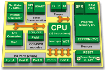
SPWM feature of micro-controller:
No, the PIC16F73/76 micro-controller does not have any special feature to generate SPWM. But it can generate PWM which is known as the CCP module of the micro-controller.

Using this CCP module we can generate a PWM signal. Now, all we need to do is changing the duty cycle of this PWM signal in a sinusoidal way so that we can get a pure sine wave after filtering this signal. Now we will do coding for SPWM. But to make a sine wave, here we are using a lookup table. This table can be self-written or you can use software to generate your sine table. I’ll use Smart Sine to generate my sine table here.
Sine table generation using Smart Sine:
This tool is very easy to use. Just put your No. of table entries, peak point, and angle. You’ll get a sine table clicking the calculate button.

So here
sin_table[32]=
{0, 25, 49, 73, 96, 118, 139, 159, 177, 193, 208, 220, 231, 239, 245, 249, 250,
249, 245, 239, 231, 220, 208, 193, 177, 159, 139, 118, 96, 73, 49, 25}; is our sine table of 32 entries.
MicroC Code:
/*******************************************************************************
* Pure sine wave generation technique using PIC microcontroller                *
* Program Written by_ Engr. Mithun K. Das                                      *
* MCU:PIC16F73; X-Tal: 20MHz; mikroC pro for PIC v7.6.0                        *
* Date: 13-04-2020                                                             *
*******************************************************************************/

unsigned char sin_table[32]=
{0, 25, 49, 73, 96, 118, 139, 159, 177, 193, 208, 220, 231, 239, 245, 249, 250,
249, 245, 239, 231, 220, 208, 193, 177, 159, 139, 118, 96, 73, 49, 25};

int duty=0;

void Interrupt() iv 0x0004 ics ICS_AUTO
{
   if (TMR2IF_bit == 1)
   {
      duty++;
      if(duty>=32)
      {
        duty=0;
        CCPR1L=0;
        asm nop;// no operation for one cycle
      }

      CCPR1L = sin_table[duty];
      TMR2IF_bit = 0;
   }
}

void main()
{
   TRISC = 0x00;//all output
   PR2 = 249;
   CCP1CON = 0x4C;
   TMR2IF_bit = 0;
   T2CON = 0x2C;
   TMR2IF_bit = 0;
   TRISC = 0;
   TMR2IE_bit = 1;
   GIE_bit = 1;
   PEIE_bit = 1;
   while(1)
   {
       //infinity loop
   }
}//end
Code Explanation:
You already know that we are using a sine table here named,
sin_table[32]=
{0, 25, 49, 73, 96, 118, 139, 159, 177, 193, 208, 220, 231, 239, 245, 249, 250,
249, 245, 239, 231, 220, 208, 193, 177, 159, 139, 118, 96, 73, 49, 25};
Now, there is no limit of the number of entry for you sine table. More the entry, more the pure sine wave you’ll get. Only one thing to know that more entry will consume more memory. Anyway, here we will use 32 entries.
That means, if we want to get a sine of 50Hz, we have 10ms in each half-cycle. So we have to use a timer interrupt which is called 32 times within this 10ms.
void Interrupt() iv 0x0004 ics ICS_AUTO
{
   if (TMR2IF_bit == 1)
   {
      duty++;
      if(duty>=32)
      {
        duty=0;
        CCPR1L=0;
        asm nop;// no operation for one cycle
      }

      CCPR1L = sin_table[duty];
      TMR2IF_bit = 0;
   }
}
Here is that interrupt where we are using Timer2. Timer2 is configured by this code here to generate interrupt 32 times within 10ms.
   PR2 = 249; //Prescaler
   CCP1CON = 0x4C; //PWM control
   TMR2IF_bit = 0;
   T2CON = 0x2C;//Timer2 control bit settings
   TMR2IF_bit = 0;
   TRISC = 0;
   TMR2IE_bit = 1;
   GIE_bit = 1;
   PEIE_bit = 1;
PR2 is Prescaler and CCP1CON is the PWM control bit. And T2CON is a timer2 control bit. You can read the datasheet to know more about this.
Test Result:
We can test the simulated result using proteus. Note that you’ll find a small spike in the sine wave because of our sine table value. If you can edit the value if required to get a 100% pure result.


Now you can try your own to generate pure sine waves using PIC16F73. To get the result with PIC16F76, just use the same hex. It will work fine.
Liked this article? Subscribe to our newsletter:
or,
Visit LabProjectsBD.com for more inspiring projects and tutorials.
Thank you!
Read more:
Connect to Raspberry Pi from your Laptop/Desktop using VNC Viewer
How to reduce noise from DC motor
Interfacing External EEPROM with PIC microcontroller
Not Enough ROM/RAM error with micro-controllers
Read ThingSpeak Channel using ESP8266 and Arduino
Caller ID detection using Arduino
Simple voltage protector for your appliances
DC/DC converter using Transistors
Simple Component Detector using PIC16F877A
Voltage Stabilizer Circuit with 4 Relays
6V Lead-Acid battery charger circuit
5 coolest multimeters you can buy
Top 5 bench power supplies you can buy
Top 5 handheld oscilloscopes you can try
Top 5 Digital Multimeters for beginners
Digital Clock with DS3231 & PIC microcontroller
Digital Clock with PIC16F676 & Seven Segment Display
Digital Clock using a PIC microcontroller & RTC DS1307
How to remove noise/garbage from the HD44780 LCD display
How to design a voltage stabilizer using a micro-controller from A to Z
Capacitor Power Supply parts calculator
Solar Charge Controller circuit & working principle of ON/OFF charge controller


21 Comments
enrique · 12/09/2020 at 3:57 pm
Hello, thank you very much for sharing your knowledge, I admire your work, I want to tell you that I am starting in this wonderful field of micro controllers, I would like to know, if someone helps me, what part of the code should I change to work at 60 Hz and 120 volts, in my country this is the standard.
Thank you very much
Mithun K. Das · 13/09/2020 at 4:37 am
Still have no design for 60Hz. But I’ll try to edit the code for 60Hz in future.
Hariharan K · 17/01/2021 at 2:12 am
Sir is this code is available in using Mplab XC8 Compiler?
Mithun K. Das · 19/01/2021 at 3:43 am
No, but maybe a little modification will fit in MPLAB
Georg · 22/02/2021 at 4:18 pm
Dear Mithun K. Das!
I got very important knowledge from the pulicized article, thank you very much! I just started learning with microcontrollers and the C programming language – I’m a beginner. I sought help for my first project. The task would be to produce a sine signal without overtones ( without distortion ). It is 50 Hz by default, but can also be switched to 67.5 Hz. This analog signal should be in a very good quality analog amplifier stage. This unit is already working perfectly. I have a PIC16F887 type microcontroller in MikroElektronika MikroC PRO and EasyPIC v7 development environment. I would like to ask if I need to change anything in the program when using the PIC16F887? How can I attach the signal directly from the microcontroller, or would it be better with a DAC device? I can’t use PROTEUS completely well yet. I design with MULTISIM software. Does step 32 generate a sufficiently “smooth” sine signal, or can the number of steps be increased?
Thanks for helping!
Mithun K. Das · 23/02/2021 at 5:04 am
It is not clear to me about the use of your sine wave signal. If you want to generate a pure signal, I’ll suggest using dsPIC. But it completely depends on your requirement and use of the signal. If you still want to use PIC MCUs then you must consider a little distortion will be in your signal. Although it is negligible % you must keep it in mind. If you need any help let me know.
Georg · 25/02/2021 at 7:27 am
Thanks for the reply! I am designing a custom built turntable. It is powered by 2 synchronous motor motors running simultaneously with a belt drive. I want to control these motors. Two frequency values are required – for speeds 33.3 and 45 (and 78 possibly). I conduct the sine wave to an amplifier stage, which produces 220 v AC at 50 Hz and 65.5 Hz. I need to pay attention to the right torque and fine frequency tuning is also required. That’s why I want to solve it using PIC. I would like to start from the example given. Fine-tuning is absolutely necessary. I can’t do that with a Quartz oscillator. I have already built a quartz oscillator control.
Mithun K. Das · 25/02/2021 at 8:34 am
In this case, I strongly recommend you use a VFD. Making an inverter using PIC MCUs will not serve your purpose. Use dsPIC or PIC24 series with Motor Controller module built-in. Also, pay attention to the IGBT driver section.
If you need professional’s help you can contact with our admin: [email protected]
Georg · 25/02/2021 at 5:50 pm
Thank you very much for the advice and thank you for the email contact as well. I need to be further informed on the subject.
Solomon · 19/06/2021 at 6:30 pm
i ve pic16f877a ,i want to generate spwm sinusoidal pulse width modulation 50hz,carrier wave 16khz,50%,also if im not rude i want to understand the calculation
thx forward
MKDas · 20/06/2021 at 5:37 am
Generating such a signal will be a little hassle with the PIC16F series. I advise using the dsPIC series instead. But if you still want to use PIC16F series then follow this instruction:
First, create a timer interrupt. Set this timer as sample/cycle rate. That means, if you want to keep 10 samples (say) for one cycle (for 10ms, half of 50Hz) then you should set the timer interrupt in a way so that it calls interrupt 10 times per 10ms. That means a 1ms timer interrupt. Now for inverters, 32 samples per cycle is a good one.
Next, set the PWM signal according to the sine table(with the same sample nos of PWM values). And then change that PWM duty according to the sine table.
I think you got the point. Now you can calculate everything.
This is the first and basic method. Another method is using CCP or Capture Compare Module. Where a prescale is used and the CCP compares that prescale and generates a PWM signal if it is changed the CCP value according to the sine table.
Felix Antwi Addo · 01/05/2022 at 7:55 pm
Hi Mithun, please how much would it cost me if you are to send me an already programmed PIC Microcontroller being any of the PIC16F73 or PIC1676. thanks.
MKDas · 04/05/2022 at 5:33 pm
Shipping Cost and IC cost.
Ismail Abdulganiyu · 18/09/2022 at 10:31 pm
Am very grateful for the useful knowledge sir, please can you help me with a system that will detect main and charge battery with LCD display…. Thanks
MKDas · 20/09/2022 at 10:53 am
This article is for learning purposes. You can find a solution to add more features if you learn it. But if you can’t then you have to take help from professionals. And if you need professional designs, you can contact me. Thanks.
Eduard · 22/10/2022 at 1:37 pm
Dear sir, I tested the code on PIC16F628 and it works flawlessly.
I’ve been trying to make it work on the PIC18F47K for a few days now, I don’t have any compilation errors, but there’s no output signal either 🙁
I know that time is very expensive and I would be very grateful if you would spare a few minutes to make the necessary changes to the code.
All the best from Romania!
MKDas · 22/10/2022 at 7:38 pm
Check MCLR first. Then Crystal settings.
Eduard · 22/10/2022 at 8:36 pm
I made the following changes and now I have output on pin 17 = 95%ON/5%OFF
code:
unsigned char sin_table[80]={125, 135, 145, 154, 164, 173, 182, 190, 198, 206,
213, 220, 226, 232, 236, 240, 244, 247, 248, 250, 250, 250, 248, 247, 244, 240,
236, 232, 226, 220, 213, 206, 198, 190, 182, 173, 164, 154, 145, 135, 125, 115,
105, 96, 86, 77, 68, 60, 52, 44, 37, 30, 24, 18, 14, 10, 6, 3, 2, 0, 0, 0, 2, 3,
6, 10, 14, 18, 24, 30, 37, 44, 52, 60, 68, 77, 86, 96, 105, 115,};
int duty=0;
void Interrupt() iv 0x008 ics ICS_AUTO
{
if (TMR1IF_bit == 1)
{
duty++;
if(duty>=80)
{
duty=0;
CCPR1L=0;
asm noc; // no operation for one cycle
}
CCPR1L = sin_table[duty];
TMR1IF_bit = 0;
}
}
void main()
{
TRISC = 0x00; //all outputs
PR1 = 249;
CCP1CON = 0x4c;
TMR1IF_bit = 0;
T1CON = 0x2C;
TMR1IF_bit = 0;
TRISC = 0;
TMR1IE_bit = 1;
GIE_bit = 1;
PEIE_bit = 1;
while(1)
{
// infinity loop
}
}// end
MKDas · 23/10/2022 at 1:30 pm
PIC18F47K40 is not same as 16F series. You have to check every register to configure properly. This way its not possible to find the error. But for 18F series, ensure the crystal, PLL, MCLR, ISR vector etc.
Rodrigo · 23/06/2023 at 11:27 am
Estimado Mithun K. Das le quiero consultar si quisiera realizar este programa en el micro 16f876/16f886 si se pudiera ya que el micro 16f73/76 no se consigue en este pais , desde ya muchas gracias .
MKDas · 02/07/2023 at 7:30 pm
possible.