In this article let’s find it out how to interface a water flow sensor with Arduino or any microcontroller. If you know the technique of calibration, you can use any sensor of a similar type to any microcontroller with these codes and calculations given here.
⚠️Disclaimer:
Working with electricity involves serious risk. Ensure you have the necessary skills and take proper safety precautions before attempting any electrical projects. Proceed at your own risk — the author assumes no responsibility for any damage, injury, or issues resulting from the use or misuse of the information provided.
All content on this website is original and protected by copyright. Please do not copy or reproduce content without permission. While most of the resources shared here are open-source and freely accessible for your learning and benefit, your respect for our intellectual effort is appreciated.
If you find our tutorials helpful, consider supporting us by purchasing related materials or sharing our work — it helps keep the content flowing.
Need help or have questions? Leave a comment below — the author is always happy to assist!
Table of Contents
What is a water flow sensor?
The Water Flow Sensor for Flow Rate & Volume Measurement using Arduino works on the principle of the Hall effect. According to the Hall effect, a voltage difference is induced in a conductor transverse to the electric current and the magnetic field perpendicular to it.
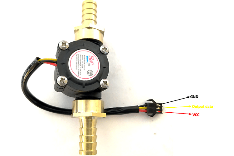
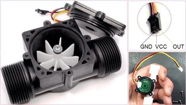
and based on that, a pulse is generated according to the water flow rate. So, if we know the pulse rate per unit of volume, we can measure the flow rate and the passed volume of water. There are different types & shapes of water flow sensors, but the principle is almost the same.
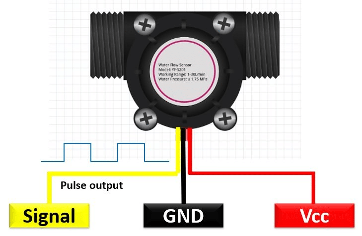
When water flows, it generates a pulse which is explained in the image below.
It generates a pulse according to the flow. Now how we can interface these sensors?
Interfacing water flow sensor:
As we need to measure the pulse and must not miss any pulses so we have to use the hardware interrupt pin of Arduino or any other microcontroller you are using. The diagram is simple:
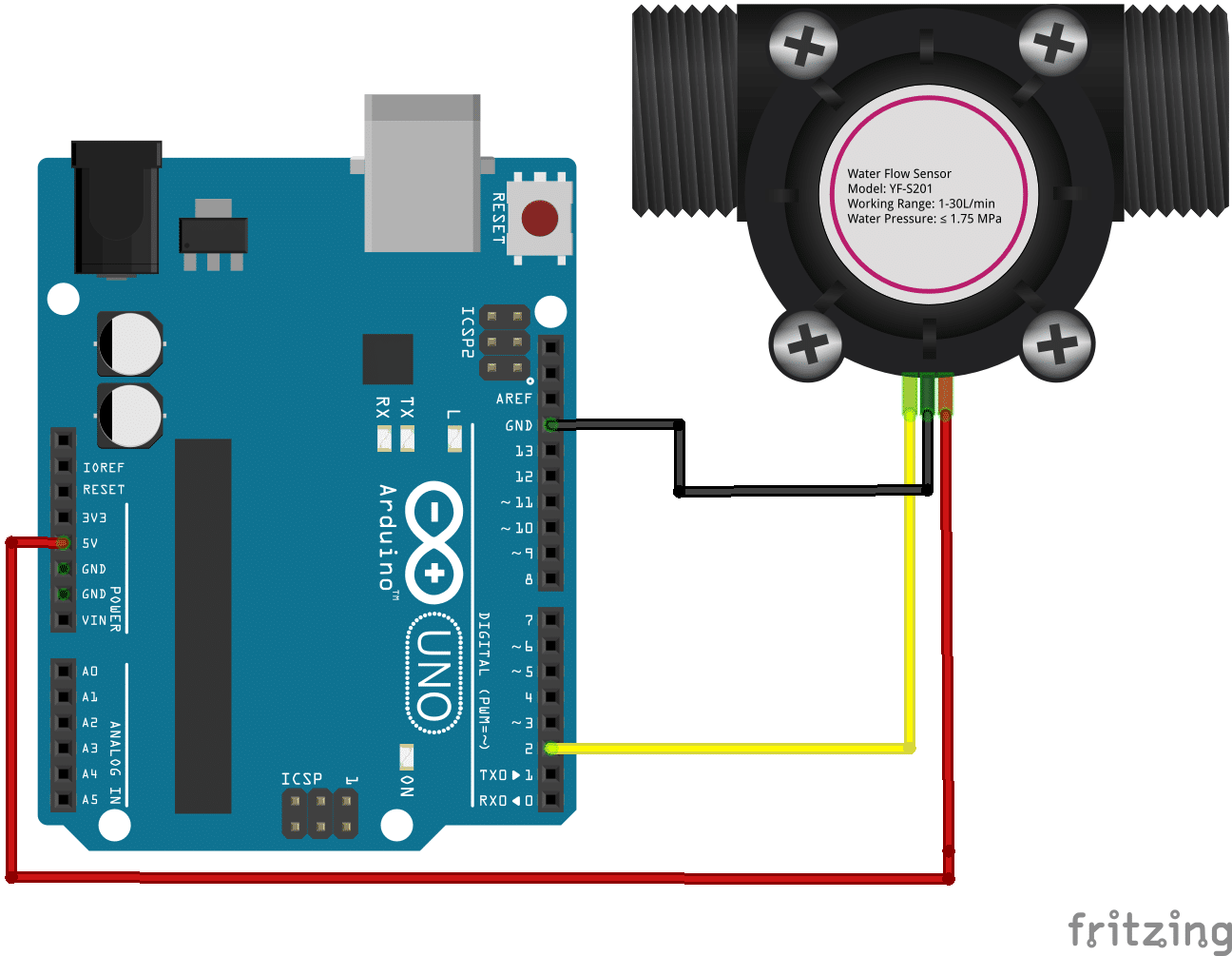
The sensor mostly works on 5V and the output is generating a pulse. Sometimes, a pull-up resistor may be required if the MCU doesn’t have any internal pull-up option. And the signal pin is connected to the hardware interrupt pin of the MCU.
Arduino Code for water flow sensor:
volatile int flow_frequency;
float vol = 0.0,l_minute;
unsigned char flowsensor = 2; // Sensor Input
unsigned long currentTime;
unsigned long cloopTime;

void flow () // Interrupt function to increment flow
{
   flow_frequency++;
}

void setup()
{
   pinMode(flowsensor, INPUT);
   attachInterrupt(digitalPinToInterrupt(flowsensor), flow, RISING); // Setup Interrupt

   currentTime = millis();
   cloopTime = currentTime;
}

void loop ()
{
   currentTime = millis();
   // Every second, calculate and print litres/hour
   if(currentTime >= (cloopTime + 1000))
   {
    cloopTime = currentTime; // Updates cloopTime
    if(flow_frequency != 0)
    {
      l_minute = (flow_frequency / 7.5); // (Pulse frequency x 60 min) / 7.5Q = flowrate in L/hour
      Serial.print("Rate: ");
      Serial.print(l_minute);
      Serial.println(" L/M");
      l_minute = l_minute/60;

      vol = vol +l_minute;
      Serial.print("Vol:");
      Serial.print(vol);
      Serial.println(" L");
      flow_frequency = 0; // Reset Counter
    }
    else {
      Serial.print("Rate: ");
      Serial.print( flow_frequency );
      Serial.println(" L/M");

      Serial.print("Vol:");
      Serial.print(vol);
      Serial.println(" L");
    }
   }
}
This is a common code for most of all water flow sensors. You need to calibrate it from sensor to sensor. So that, you can measure with any similar flow sensor.
Calibration:
What I personally do for calibration is, first keep the code as it is and then measure 10Ltrs of water which is flow through the sensor. Just ensure that 10Ltrs of water is perfectly measured. Then simply take the reading from the sensor. Say the sensor measured 14.5Ltrs but in practice, you took 10Ltrs of water. So what will be the calibration factor?
Calibration factor = 10.00/14.5 = 0.6896.
So if you divide this by the sensor reading:
vol = vol +(l_minute/0.6896);
Then you can get the exact calibrated result of volume. this is the easy way and if you want to go further, you can calibrate the flow rate too.
Conclusion:
Now, you know how to interface almost any water flow sensor those works on the same principle. And you know how to calibrate it. This is how every sensor gives a perfect reading. And if you use this sensor in any project that is regularly use you must need to measure it perfectly. In this case, there is no way without calibrating. Because each sensor may be different in reading. So better calibrate the readings.
Read more on:
- How to scan I2C slaves using an Arduino
- Interfacing ID20LA with Arduino
- Digital Clock with Temperature & Humidity display
- How to interface ST7567 display with Arduino
- How to interface the EM-18 RFID reader module with an Arduino
- How to interface ESP8266 with STM32
Liked this article? Subscribe to our newsletter:
or,
Visit LabProjectsBD.com for more inspiring projects and tutorials.
Thank you!


0 Comments