Learn how to interface a 16×2 LCD with an STM32 microcontroller in this step-by-step guide. Discover the hardware connections and example code required to display text on an LCD screen and create a basic user interface for embedded applications.
⚠️Disclaimer:
Working with electricity involves serious risk. Ensure you have the necessary skills and take proper safety precautions before attempting any electrical projects. Proceed at your own risk — the author assumes no responsibility for any damage, injury, or issues resulting from the use or misuse of the information provided.
All content on this website is original and protected by copyright. Please do not copy or reproduce content without permission. While most of the resources shared here are open-source and freely accessible for your learning and benefit, your respect for our intellectual effort is appreciated.
If you find our tutorials helpful, consider supporting us by purchasing related materials or sharing our work — it helps keep the content flowing.
Need help or have questions? Leave a comment below — the author is always happy to assist!
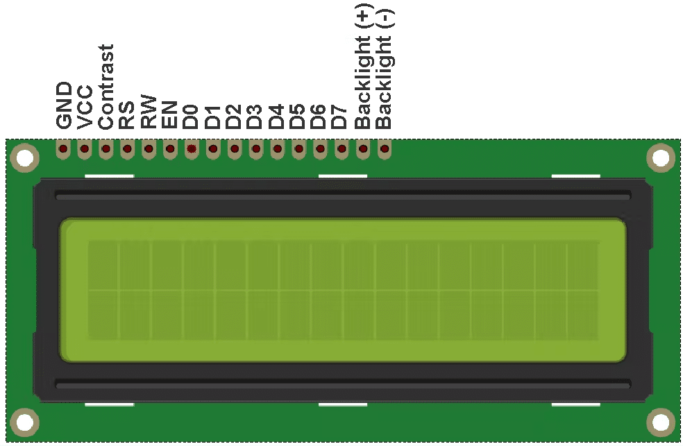
About 16×2 LCD:
16×2 LCD is named so because; it has 16 Columns and 2 Rows. There are a lot of combinations available like 8×1, 8×2, 10×2, 16×1, etc. But the most used one is the 16*2 LCD, hence we are using it here.
All the above-mentioned LCD displays will have 16 Pins and the programming approach is also the same hence the choice is left to you. Below is the Pinout and Pin Description of the 16×2 LCD Module:
Interfacing 16×2 LCD with STM32:
Interfacing a 16×2 LCD with an STM32 microcontroller is a common task in embedded systems. In this task, we need to connect the LCD to the STM32 and write code to control it. Here are the steps involved in interfacing a 16×2 LCD with an STM32:
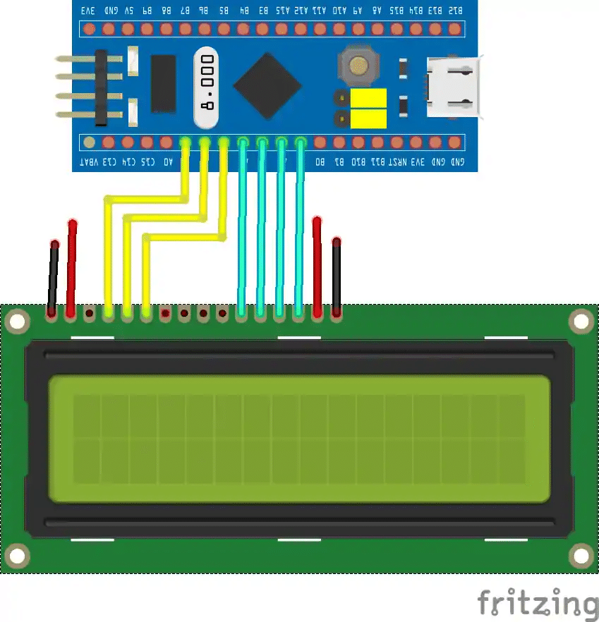
- Hardware connections: Connect the 16×2 LCD to the STM32 using the following connections:
- Connect the RS pin of the LCD to a GPIO pin of the STM32.
- Connect the EN pin of the LCD to a GPIO pin of the STM32.
- Connect the D4-D7 pins of the LCD to the four GPIO pins of the STM32.
- Connect the VSS and RW pins of the LCD to the ground.
- Connect the VDD and K pins of the LCD to a +5V power supply and ground, respectively.
- Initialize GPIO pins: In the code, initialize the GPIO pins connected to the LCD as output pins.
- Write initialization code: Send initialization commands to the LCD to set it up for communication. This involves sending a series of commands such as setting the display mode, clearing the screen, etc.
- Write code to display data: Use the LCD commands to display data on the screen. This involves sending commands to set the cursor position and sending the actual data to be displayed.
Here is an example code to interface a 16×2 LCD with an STM32:
#include "stm32f4xx.h"

#define RS_Pin GPIO_PIN_12
#define RS_GPIO_Port GPIOB
#define EN_Pin GPIO_PIN_13
#define EN_GPIO_Port GPIOB
#define D4_Pin GPIO_PIN_14
#define D4_GPIO_Port GPIOB
#define D5_Pin GPIO_PIN_15
#define D5_GPIO_Port GPIOB
#define D6_Pin GPIO_PIN_10
#define D6_GPIO_Port GPIOB
#define D7_Pin GPIO_PIN_11
#define D7_GPIO_Port GPIOB

void LCD_SendCommand(uint8_t command);
void LCD_SendData(uint8_t data);
void LCD_Clear(void);
void LCD_WriteString(char* str);

void LCD_Init(void) {
  LCD_SendCommand(0x02);
  LCD_SendCommand(0x28);
  LCD_SendCommand(0x0C);
  LCD_SendCommand(0x06);
}

void LCD_SendCommand(uint8_t command) {
  HAL_GPIO_WritePin(RS_GPIO_Port, RS_Pin, GPIO_PIN_RESET);

  HAL_GPIO_WritePin(D4_GPIO_Port, D4_Pin, (command >> 4) & 1);
  HAL_GPIO_WritePin(D5_GPIO_Port, D5_Pin, (command >> 5) & 1);
  HAL_GPIO_WritePin(D6_GPIO_Port, D6_Pin, (command >> 6) & 1);
  HAL_GPIO_WritePin(D7_GPIO_Port, D7_Pin, (command >> 7) & 1);

  HAL_GPIO_WritePin(EN_GPIO_Port, EN_Pin, GPIO_PIN_SET);
  HAL_Delay(1);
  HAL_GPIO_WritePin(EN_GPIO_Port, EN_Pin, GPIO_PIN_RESET);
  HAL_Delay(1);

  HAL_GPIO_WritePin(D4_GPIO_Port, D4_Pin, command & 1);
  HAL_GPIO_WritePin(D5_GPIO_Port, D5_Pin, (command >> 1) & 1);
  HAL_GPIO_WritePin(D6_GPIO_Port, D6_Pin, (command >> 2) & 1);
  HAL_GPIO_WritePin(D7_GPIO_Port, D7_Pin, (command >> 3) & 1);

  HAL_GPIO_WritePin(EN_GPIO_Port, EN_Pin, GPIO_PIN_SET);
  HAL_Delay(1);
  HAL_GPIO_WritePin(EN_GPIO_Port, EN_Pin, GPIO_PIN_RESET);
  HAL_Delay(1);
}

void LCD_SendData(uint8_t data) {
  HAL_GPIO_WritePin(RS_GPIO_Port, RS_Pin, GPIO_PIN_SET);

  HAL_GPIO_WritePin(D4_GPIO_Port, D4_Pin, (data >> 4) & 1);
  HAL_GPIO_WritePin(D5_GPIO_Port, D5_Pin, (data >> 5) & 1);
  HAL_GPIO_WritePin(D6_GPIO_Port, D6_Pin, (data >> 6) & 1);
  HAL_GPIO_WritePin(D7_GPIO_Port, D7_Pin, (data >> 7) & 1);

  HAL_GPIO_WritePin(EN_GPIO_Port, EN_Pin, GPIO_PIN_SET);
  HAL_Delay(1);
  HAL_GPIO_WritePin(EN_GPIO_Port, EN_Pin, GPIO_PIN_RESET);
  HAL_Delay(1);

  HAL_GPIO_WritePin(D4_GPIO_Port, D4_Pin, data & 1);
  HAL_GPIO_WritePin(D5_GPIO_Port, D5_Pin, (data >> 1) & 1);
  HAL_GPIO_WritePin(D6_GPIO_Port, D6_Pin, (data >> 2) & 1);
  HAL_GPIO_WritePin(D7_GPIO_Port, D7_Pin, (data >> & 1);
HAL_GPIO_WritePin(EN_GPIO_Port, EN_Pin, GPIO_PIN_SET);
HAL_Delay(1);
HAL_GPIO_WritePin(EN_GPIO_Port, EN_Pin, GPIO_PIN_RESET);
HAL_Delay(1);
}

void LCD_Clear(void) {
LCD_SendCommand(0x01);
HAL_Delay(2);
}

void LCD_WriteString(char* str) {
while(*str) {
LCD_SendData(*str++);
HAL_Delay(1);
}
}

int main(void) {
HAL_Init();

RCC->AHB1ENR |= RCC_AHB1ENR_GPIOBEN;

GPIO_InitTypeDef GPIO_InitStruct = {0};
GPIO_InitStruct.Pin = RS_Pin | EN_Pin | D4_Pin | D5_Pin | D6_Pin | D7_Pin;
GPIO_InitStruct.Mode = GPIO_MODE_OUTPUT_PP;
GPIO_InitStruct.Pull = GPIO_NOPULL;
GPIO_InitStruct.Speed = GPIO_SPEED_FREQ_LOW;
HAL_GPIO_Init(GPIOB, &GPIO_InitStruct);

LCD_Init();

LCD_Clear();
LCD_WriteString("Hello World!");

while (1) {
}
}
In this example, the 16×2 LCD is connected to the STM32 microcontroller using the following pin configuration:
- RS pin is connected to PB12
- EN pin is connected to PB13
- D4 pin is connected to PB14
- D5 pin is connected to PB15
- D6 pin is connected to PB10
- D7 pin is connected to PB11
The code initializes the GPIO pins for the LCD and defines functions for sending commands and data to the LCD. The LCD_Init() function initializes the LCD and the LCD_Clear() function clears the LCD screen. The LCD_WriteString() function writes a string to the LCD.
In the main() function, the GPIO pins are initialized, the LCD is initialized, and the string “Hello World!” is written to the LCD. The microcontroller then enters an infinite loop.
Note that the code uses a 4-bit interface to communicate with the LCD, which requires sending data in two 4-bit nibbles. This is done using the HAL_GPIO_WritePin() function to set the data pins and the HAL_GPIO_ReadPin() function to read the busy flag of the LCD. The HAL_Delay() function is used to introduce delays between commands to ensure the LCD has enough time to process the commands.
Conclusion:
Overall, interfacing a 16×2 LCD with an STM32 microcontroller requires a few simple hardware connections and some basic software programming. By following the steps and example code above, it is possible to display text on the LCD screen and create a basic user interface for a wide range of embedded applications.
Read more on:
- How to interface ESP8266 with STM32
- How to interface DHT11 with STM32
- Designing a BMS with STM32
- STM32 Development Boards: A Guide for Beginners
- How to interface the EM18 RFID module with STM32
- Learn how to use the Real-time Clock (RTC) of STM32
Liked this article? Subscribe to our newsletter:
or,
Visit LabProjectsBD.com for more inspiring projects and tutorials.
Thank you!


5 Comments
Rafiu Ajape · 27/03/2023 at 4:47 pm
Good day sir. Thank you for the good work. Pls what compiler do you for this STM microcontroller boards in case of simulation purposes.
MKDas · 28/03/2023 at 11:45 am
no simulation, direct debug. STM32CubeIDE
Asimiyu · 04/04/2023 at 10:04 pm
Thank you sir
DINESH KUMAR · 24/11/2023 at 10:03 am
what simulation is suitable for STM32 family other than proteus simulation ?????
MKDas · 29/11/2023 at 8:29 pm
hardware simulation(!). Debug in real hardware. Simulation is for kids.