Current transformers (CTs) are the simplest isolated way to measure AC current with a microcontroller. This guide shows how to size the burden resistor, bias the signal for a single-supply ADC, compute true RMS in firmware and calibrate it, with values from a charger monitor we built.
- Why a CT instead of a shunt for AC current
- Choosing the burden resistor (with a worked example)
- Biasing the signal for a 3.3 V ADC
- Sampling and true RMS in C
- Using external 200:5 A CTs
- Calibration and safety
Table of Contents
Why use a current transformer?
A shunt resistor works well for DC, but on AC mains it puts your measurement circuit at line potential. A CT gives galvanic isolation for free: the primary is the conductor carrying the load current, and the secondary delivers a much smaller current, proportional to the primary, into your circuit.
A small PCB CT rated 5 A : 5 mA has a turns ratio of 1000:1. At 5 A in the primary, 5 mA rms flows in the secondary. Your job is to turn that current into a voltage the ADC can read, without saturating the CT.
The front-end circuit
- Burden resistor (Rb) converts secondary current to voltage: V = Isec × Rb.
- Bias divider (two equal resistors and a capacitor) shifts the AC signal up to Vref/2, so both half-cycles stay inside 0 to 3.3 V.
- Series resistor and capacitor at the ADC pin limit fault current and filter high-frequency noise.
Choosing the burden resistor
The peak voltage across the burden must fit inside half the ADC range (with mid-rail bias), with some headroom:
Rb = Vpeak,allowed / (√2 × Iprimary,max / N)
Worked example: 5 A, 1000:1 CT, 3.3 V ADC
| Step | Value |
|---|---|
| Secondary current at 5 A | 5 A / 1000 = 5 mA rms |
| Allowed peak (90% of Vref/2) | 0.9 × 1.65 V = 1.485 V |
| Exact burden | 1.485 / (1.414 × 0.005) = 210 Ω |
| Chosen value (E24, rounded down) | 200 Ω |
| Peak at the ADC with 200 Ω | 1.414 V around the 1.65 V bias |
| Burden dissipation | (5 mA)² × 200 Ω = 5 mW |
Check the CT datasheet for its maximum burden. If your calculated value is above it, the CT will saturate at high current and read low. Use our CT burden resistor calculator to try other ratios and currents.
Sampling and true RMS in firmware
- Sample fast enough to capture harmonics: 5 kHz gives 100 samples per 50 Hz cycle.
- Process a whole number of cycles (for example 4 cycles = 80 ms at 50 Hz), otherwise the RMS value ripples.
- Remove the DC bias by subtracting the average of the samples, not a fixed number; the bias drifts with temperature and resistor tolerance.
- Use DMA to fill the sample buffer so the CPU only does the math.
#include <math.h>
#include <stdint.h>

/* buf: raw 12-bit ADC samples over a whole number of mains cycles
   vref: ADC reference in volts, rb: burden in ohms
   ratio: total CT ratio (e.g. 1000 for 5 A : 5 mA)
   cal: gain correction from calibration (1.0 = none)        */
float ct_rms_amps(const uint16_t *buf, uint32_t n,
                  float vref, float rb, float ratio, float cal)
{
    float mean = 0.0f;
    for (uint32_t i = 0; i < n; i++) mean += buf[i];
    mean /= (float)n;                       /* DC bias, about Vref/2 */

    float acc = 0.0f;
    for (uint32_t i = 0; i < n; i++) {
        float d = (float)buf[i] - mean;     /* remove the bias */
        acc += d * d;
    }
    float v_rms = sqrtf(acc / (float)n) * vref / 4095.0f;
    return (v_rms / rb) * ratio * cal;      /* primary current, A rms */
}
On an STM32, run the ADC in scan mode with DMA and a timer trigger. Each channel then has a fixed, known sampling rate, and you can compute RMS for several CTs from one buffer.
Measuring hundreds of amps with external CTs
For large currents, use a standard external CT (for example 200:5 A) on the busbar and pass its 5 A secondary through the 5 A : 5 mA PCB CT. The total ratio is the product: 40 × 1000 = 40,000:1, so 200 A in the busbar gives 5 mA at the burden. Make the external CT ratio a setting in your product so one board covers many installations.
Calibration
- Store one gain value per channel in non-volatile memory (EEPROM or FRAM).
- Calibrate against a reference clamp meter at a current near the top of the range.
- Protect the calibration screen or command so end users cannot change it accidentally.
Safety notes
- Never open-circuit the secondary of a loaded CT. Large external CTs can generate dangerous voltages without their burden. Use shorting terminal blocks for maintenance.
- Keep creepage and clearance between the primary conductor and the low-voltage circuit as the CT and your safety standard require.
- Ground the bias or burden reference only at one point to avoid ground loops.
Where we used this
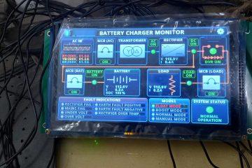
This front end measures the three line currents in our industrial battery charger monitor, with 200 Ω burdens, selectable external CT ratios and per-channel calibration stored in FRAM.
Building a charger, inverter or monitoring product? We design measurement front ends, firmware and complete controllers. Message us on WhatsApp or use the contact form.



0 Comments