Measuring three-phase mains with a microcontroller needs isolation, scaling and some care in firmware. This guide uses small potential transformers (PTs) to measure phase and line-to-line voltages, detect a failed phase and check phase sequence, based on a charger monitor we built.
- Why use PTs for mains voltage sensing
- Scaling a 220:12 V PT into a 3.3 V ADC
- Phase-to-neutral and line-to-line RMS
- Detecting phase failure and phase sequence
- Calibration and safety
Table of Contents
Why potential transformers?
A resistor divider straight from the mains can measure voltage, but it ties your whole circuit to line potential. A small PT per phase gives isolation, so the microcontroller, display and communication ports stay safe to touch and easy to connect to other equipment.
The front-end circuit
Scaling a 220:12 V PT for a 3.3 V ADC
Design for the highest voltage you must measure without clipping, not the nominal one. With a 220:12 V PT:
| Condition | Phase voltage | PT secondary (rms) | Secondary peak | Peak at ADC with 150k/10k (÷16) |
|---|---|---|---|---|
| Nominal | 230 V | 12.5 V | 17.7 V | 1.11 V |
| High mains | 250 V | 13.6 V | 19.3 V | 1.21 V |
| Surge margin | 300 V | 16.4 V | 23.1 V | 1.45 V |
With the signal biased at 1.65 V, a 1.45 V peak still fits inside 0–3.3 V, so the reading stays valid up to about 300 V phase-to-neutral. Use our voltage divider calculator to check other ratios. Remember that a lightly loaded PT outputs more than its nameplate voltage, so measure it and set the final scale by calibration.
Phase-to-neutral and line-to-line voltages
Compute each phase RMS the same way as for current: remove the bias, square, average over whole cycles and take the square root. For line-to-line voltages, do not just multiply by √3; that is only true when the phases are balanced. Instead, subtract the two phase samples taken in the same ADC scan and compute the RMS of the difference:
#include <math.h>
#include <stdint.h>

/* a, b: bias-removed samples of two phases taken in the same ADC scan
   k: volts per count referred to the PT primary (divider x PT ratio x cal) */
float line_to_line_rms(const int16_t *a, const int16_t *b, uint32_t n, float k)
{
    float acc = 0.0f;
    for (uint32_t i = 0; i < n; i++) {
        float d = (float)(a[i] - b[i]);     /* v_RY = v_R - v_Y */
        acc += d * d;
    }
    return sqrtf(acc / (float)n) * k;
}
If the ADC converts channels one after another, there is a small time skew between R, Y and B samples. At 50 Hz and a few microseconds per channel the error is tiny, but for best accuracy use simultaneous-sampling ADCs or interpolate.
Detecting a failed phase
- Treat a phase as good inside a window, for example 180–250 V phase-to-neutral, and as failed outside it.
- Add hysteresis and a short delay so a single dip does not trip the alarm.
- Only report line-to-line values that involve two good phases; show the failed phase clearly instead.
- Switch the main contactor or breaker indication on only when all three phases are good.
Frequency and phase sequence
Detect rising zero crossings on each phase (with a little hysteresis). The time between crossings on one phase gives the frequency; the order in which R, Y and B cross gives the sequence. R → Y → B with about 6.67 ms between them at 50 Hz is the correct rotation; anything else should raise a phase-sequence fault before motors or rectifiers start.
Calibration and safety
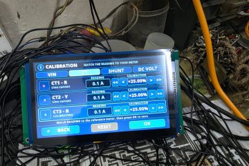
- Calibrate each channel against a true-RMS meter and store the gain in non-volatile memory.
- Fuse each PT primary and keep mains creepage distances on the PCB.
- Choose PTs with a suitable insulation rating and test voltage for your installation category.
Where we used this
This approach measures the three-phase input of our industrial battery charger monitor, which shows RY, YB and BR line voltages, flags a failed phase and only shows the AC breaker as ON when all three phases are good.
Building a charger, inverter or monitoring product? We design measurement front ends, firmware and complete controllers. Message us on WhatsApp or use the contact form.



0 Comments