I was looking for a good library to interface multiplexed Seven Segment with Arduino. But unfortunately, found no such good library that I can use as myself. Each one making trouble in Proteus simulation. Some examples I found over the internet, not explained properly or not simplified at all. That is why I wrote my own code for multiplexed Seven segment display for Arduino that can be used as I want. Maybe this article will help you a lot.
⚠️Disclaimer:
Working with electricity involves serious risk. Ensure you have the necessary skills and take proper safety precautions before attempting any electrical projects. Proceed at your own risk — the author assumes no responsibility for any damage, injury, or issues resulting from the use or misuse of the information provided.
All content on this website is original and protected by copyright. Please do not copy or reproduce content without permission. While most of the resources shared here are open-source and freely accessible for your learning and benefit, your respect for our intellectual effort is appreciated.
If you find our tutorials helpful, consider supporting us by purchasing related materials or sharing our work — it helps keep the content flowing.
Need help or have questions? Leave a comment below — the author is always happy to assist!
Table of Contents
Basics of seven segment display
Before we start, we must know the basics of seven-segment displays. If you know this already, just go to the next stage. Anyway, most of the seven-segment are made with LED blocks. There are other two types of segments in the market, crystal-based, and tube-based. But the LED-based one is the most common.
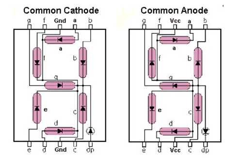
As you see, the segments are two types according to the LED configuration. One is Common Cathode another is Common Anode. If you want to drive these segments, you just need to maintain the right voltage & polarity. Now, these segments have a total of 8 segment pins and two shorted common pins. If we attach 3 or 4 same types of segments in a line and keep the 8 segment pins in common and shorted pins individual for each digit, it will form a multiplexed 7Segment display of 3×1 or 4×1.
The benefit of this type of display is, we have the common 8 pins for each segment and individual data pins for each digit. In this way, the I/O pin can be reduced and it becomes more suitable for circuit placement.
But problem is, driving this type of multiplexed display is not as simple as single-digit driving. If you have a set of outputs for the segment pins, you can activate only one digit each time to display it correctly.

I found an animation for multiplexed Seven segment display. As you can see, the data pins are setting a configuration for a number and the data pin is activating the individual digits. This process going on sequentially. If we do this job faster I mean within 10ms, our eye will see this as a 4 digit number of 1238. That’s the secrete of driving multiplexed seven segment displays.
Drawing the circuit diagram:
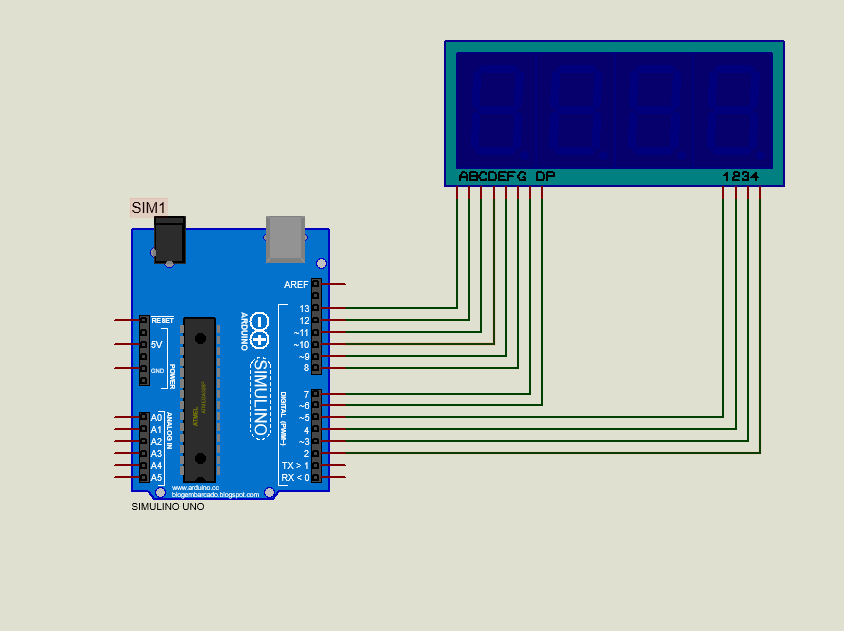
Now, to test this process of multiplexing, we need to make a circuit diagram first. Let’s draw a circuit diagram like this in Proteus:
Now, we need to write our code for this circuit diagram. But first, we need to simplify our working mechanism to drive the multiplexed 7Segment display.
You may find this helpful: How to make a DC Voltmeter with Arduino & Seven Segment Display
Simplified working mechanism:
Pattern generation:
From that animated image, you know we need to generate a pattern first for each number.
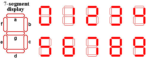
To show 0, we need to turn on some LEDs of our segment. a,b,c,d,e,f are 1 and g = 0; Then if forms ‘0’ in display. Similarly, we can generate a pattern for each number from 0 to 9. Note that, if you want to display characters, you can do that too. But for the first project, limit in numbers only.
As we are going to use Arduino, we have to make these patterns according to Arduino style. In Arduino, 1 = HIGH and 0 = LOW.
If we take an array for this, we can store all the patterns in that array. Now, as we have to use 8 individual pins for segment patterns and also have to create 10 of this type of pattern, so we must arrange an array with dual dimensions.
Now we can call the pattern of any number and can set our 8 pins according to our segment pattern. We’ll see more about this later in the code section below.
Timing generation:
After generating our pattern, we need to generate a timing. I mentioned earlier that, if we do the animation faster we can see one single picture of a complete number of 4 digits. Whatever 3,4 or more digits, we have to do all the process within 0.25 seconds. Then we can see a still number of multiple digits. That means, if we use 4 digit display and maintain timing of 5ms for each update we can see a single number of 4 digits on the display without any blinks.
For this timing generation, we can use Timer modules of Arduino. Setting the interrupt in 5000us or 5ms, we can easily generate our timing
Now we can write our code for our project.
Arduino Code:
#include <TimerOne.h>
const int segment_pins[] = {13, 12, 11, 10, 9, 8, 7, 6}; //segments a to g
const int digit_pins[] = {5, 4, 3, 2}; // 4digits
const int digit_number = 4;//for 4 digit segment
byte dot_position;//set dot position from right side.
bool dot_point=false;// having dot or not, true = have dot, false = no dot.

const int segment_array[10][8] = // for common cathode segment only
{
  {HIGH, HIGH, HIGH, HIGH, HIGH, HIGH, LOW, LOW}, //0
  {LOW, HIGH, HIGH, LOW, LOW, LOW, LOW, LOW},     //1
  {HIGH, HIGH, LOW, HIGH, HIGH, LOW, HIGH, LOW},  //2
  {HIGH, HIGH, HIGH, HIGH, LOW, LOW, HIGH, LOW},  //3
  {LOW, HIGH, HIGH, LOW, LOW, HIGH, HIGH, LOW},   //4
  {HIGH, LOW, HIGH, HIGH, LOW, HIGH, HIGH, LOW},  //5
  {HIGH, LOW, HIGH, HIGH, HIGH, HIGH, HIGH, LOW}, //6
  {HIGH, HIGH, HIGH, LOW, LOW, LOW, LOW, LOW},    //7
  {HIGH, HIGH, HIGH, HIGH, HIGH, HIGH, HIGH, LOW},//8
  {HIGH, HIGH, HIGH, HIGH, LOW, HIGH, HIGH, LOW}, //9
};


void int_sev_segment()
{
  for (int k = 0; k < 8; k++)
  {
    pinMode(segment_pins[k], OUTPUT);//I/O settings
  }
  for (int k = 0; k < digit_number; k++)
  {
    pinMode(digit_pins[k], OUTPUT);//I/O settings
  }
  for (int k = 0; k < 8; k++)
  {
    digitalWrite(segment_pins[k], LOW);//keep low
  }
  for (int k = 0; k < digit_number; k++)
  {
    digitalWrite(digit_pins[k], HIGH);//keep high = disable segments (CC)
  }
  Timer1.initialize(5000);//5000us = 5ms
  Timer1.attachInterrupt(display_segment);
}


char digits[5];
void display_7segment(int number, byte dot)
{
  digits[3] = number / 1000u;//extract 1000th digit
  digits[2] = (number / 100u) % 10u;//extract 100th digit
  digits[1] = (number / 10u) % 10u;//extract 10th digit
  digits[0] = (number / 1u) % 10u;//extract 1st digit
  dot_position = dot;
}


int digit_position = 0;
void display_segment(void) // called periodically using timer interrupt
{
  for (int k = 0; k < digit_number; k++)
  {
    digitalWrite(digit_pins[k], HIGH);//reset digit pins
  }
  if (digit_position > 3)digit_position = 0;

  for (int k = 0; k < 8; k++) //print the a to g segment pins
  {
    digitalWrite(segment_pins[k], segment_array[digits[digit_position]][k]);
    if (digit_position == dot_position && dot_point == true)
    {
      digitalWrite(segment_pins[7], HIGH);//print dot point
    }
  }

  if (digit_position == 3)
  {
    digitalWrite(digit_pins[0], LOW);
    digitalWrite(digit_pins[1], HIGH);
    digitalWrite(digit_pins[2], HIGH);
    digitalWrite(digit_pins[3], HIGH);
  }
  else if (digit_position == 2)
  {
    digitalWrite(digit_pins[0], HIGH);
    digitalWrite(digit_pins[1], LOW);
    digitalWrite(digit_pins[2], HIGH);
    digitalWrite(digit_pins[3], HIGH);
  }
  else if (digit_position == 1)
  {
    digitalWrite(digit_pins[0], HIGH);
    digitalWrite(digit_pins[1], HIGH);
    digitalWrite(digit_pins[2], LOW);
    digitalWrite(digit_pins[3], HIGH);
  }
  else if (digit_position == 0)
  {
    digitalWrite(digit_pins[0], HIGH);
    digitalWrite(digit_pins[1], HIGH);
    digitalWrite(digit_pins[2], HIGH);
    digitalWrite(digit_pins[3], LOW);
  }
  digit_position++;
}


int cnt = 0;
void setup()
{

  int_sev_segment();//initialize seven segment program

}

void loop()
{

  cnt++;
  display_7segment(cnt, 1); //display value of cnt, dot in position 1 from right side
  delay(500);

}


// end
Code explanation:
#include <TimerOne.h>
const int segment_pins[] = {13, 12, 11, 10, 9, 8, 7, 6}; //segments a to g
const int digit_pins[] = {5, 4, 3, 2}; // 4digits
const int digit_number = 4;//for 4 digit segment
byte dot_position;//set dot position from right side.
bool dot_point=false;// having dot or not, true = have dot, false = no dot.
Here, TimerOne.h is used for a timer interrupt. We mentioned earlier that we will not use any library for multiplexed Seven segment displays. But Timers is not that library to Seven Segment. We have to use this to active interrupts.
Segment_Pins array contains the individual pins for segments a to g. And other parameters are easy to understand. If you do not want to keep the dot point, set dot_point=false.
const int segment_array[10][8] = // for common cathode segment only
{
  {HIGH, HIGH, HIGH, HIGH, HIGH, HIGH, LOW, LOW}, //0
  {LOW, HIGH, HIGH, LOW, LOW, LOW, LOW, LOW},     //1
  {HIGH, HIGH, LOW, HIGH, HIGH, LOW, HIGH, LOW},  //2
  {HIGH, HIGH, HIGH, HIGH, LOW, LOW, HIGH, LOW},  //3
  {LOW, HIGH, HIGH, LOW, LOW, HIGH, HIGH, LOW},   //4
  {HIGH, LOW, HIGH, HIGH, LOW, HIGH, HIGH, LOW},  //5
  {HIGH, LOW, HIGH, HIGH, HIGH, HIGH, HIGH, LOW}, //6
  {HIGH, HIGH, HIGH, LOW, LOW, LOW, LOW, LOW},    //7
  {HIGH, HIGH, HIGH, HIGH, HIGH, HIGH, HIGH, LOW},//8
  {HIGH, HIGH, HIGH, HIGH, LOW, HIGH, HIGH, LOW}, //9
};
In the working mechanism section, we came to know that we must generate a dual dimensional array for our display. Here in this segment_array, we set the pin outputs in patterns to generate an individual number on the segment.
void int_sev_segment()
{
  for (int k = 0; k < 8; k++)
  {
    pinMode(segment_pins[k], OUTPUT);//I/O settings
  }
  for (int k = 0; k < digit_number; k++)
  {
    pinMode(digit_pins[k], OUTPUT);//I/O settings
  }
  for (int k = 0; k < 8; k++)
  {
    digitalWrite(segment_pins[k], LOW);//keep low
  }
  for (int k = 0; k < digit_number; k++)
  {
    digitalWrite(digit_pins[k], HIGH);//keep high = disable segments (CC)
  }
  Timer1.initialize(5000);//5000us = 5ms
  Timer1.attachInterrupt(display_segment);
}
In this initialization section, we initialized the input/output configuration and timer interrupt.
char digits[5];
void display_7segment(int number, byte dot)
{
  digits[3] = number / 1000u;//extract 1000th digit
  digits[2] = (number / 100u) % 10u;//extract 100th digit
  digits[1] = (number / 10u) % 10u;//extract 10th digit
  digits[0] = (number / 1u) % 10u;//extract 1st digit
  dot_position = dot;
}
This display_7segment function is extracting digits of different positions which is stored in a digits array.
int digit_position = 0;
void display_segment(void) // called periodically using timer interrupt
{
  for (int k = 0; k < digit_number; k++)
  {
    digitalWrite(digit_pins[k], HIGH);//reset digit pins
  }
  if (digit_position > 3)digit_position = 0;

  for (int k = 0; k < 8; k++) //print the a to g segment pins
  {
    digitalWrite(segment_pins[k], segment_array[digits[digit_position]][k]);
    if (digit_position == dot_position && dot_point == true)
    {
      digitalWrite(segment_pins[7], HIGH);//print dot point
    }
  }

  if (digit_position == 3)
  {
    digitalWrite(digit_pins[0], LOW);
    digitalWrite(digit_pins[1], HIGH);
    digitalWrite(digit_pins[2], HIGH);
    digitalWrite(digit_pins[3], HIGH);
  }
  else if (digit_position == 2)
  {
    digitalWrite(digit_pins[0], HIGH);
    digitalWrite(digit_pins[1], LOW);
    digitalWrite(digit_pins[2], HIGH);
    digitalWrite(digit_pins[3], HIGH);
  }
  else if (digit_position == 1)
  {
    digitalWrite(digit_pins[0], HIGH);
    digitalWrite(digit_pins[1], HIGH);
    digitalWrite(digit_pins[2], LOW);
    digitalWrite(digit_pins[3], HIGH);
  }
  else if (digit_position == 0)
  {
    digitalWrite(digit_pins[0], HIGH);
    digitalWrite(digit_pins[1], HIGH);
    digitalWrite(digit_pins[2], HIGH);
    digitalWrite(digit_pins[3], LOW);
  }
  digit_position++;
}
This function is being called periodically in 5ms intervals. Here, step by step we are doing some important works. First, we are disabling all 4 digits by setting the digit pins HIGH. Then the position counter is being reset to 0 if it is over 3.
for (int k = 0; k < 8; k++) //print the a to g segment pins
  {
    digitalWrite(segment_pins[k], segment_array[digits[digit_position]][k]);
    if (digit_position == dot_position && dot_point == true)
    {
      digitalWrite(segment_pins[7], HIGH);//print dot point
    }
  }
And the most important work is done here. As you can see, we are calling that dual dimensional array here and setting our segment array pins according to the digits of each position. Also if there is any dot, we have to print that too.
if (digit_position == 3)
  {
    digitalWrite(digit_pins[0], LOW);
    digitalWrite(digit_pins[1], HIGH);
    digitalWrite(digit_pins[2], HIGH);
    digitalWrite(digit_pins[3], HIGH);
  }
...
Then we are activating each digit one at a time-shifting to the next and rolling to position 0 when done. As this ISR is being called in each 5ms interval, so we are printing our digits one by one within 5×4 = 20ms.
In the loop function, we are simply calling this to count a number and display that on our multiplexed segment.
Test result:
Conclusion:
In the end, I hope you understood the project and now you can practice yourself. After practice, I’ll suggest making one for yourself and share here. Anywhere in the middle if you need any help, just ask. I’ll try my best to help you.
Thank you very much. Enjoy!
Liked this article? Subscribe to our newsletter:
or,
Visit LabProjectsBD.com for more inspiring projects and tutorials.
Thank you!
Check this out: 5 coolest multimeters you can buy


2 Comments
Rajbir Dass · 07/03/2021 at 6:23 pm
Sir please give me code for ac 220v/ 100A current meter code in 3digit 7segment display for Arduino
Mithun K. Das · 08/03/2021 at 5:23 am
You can make it yourself. Kindly read the high current sensing article besides this article. If you can not understand let me know. Thanks.