Data Logger is a device that records data periodically with time and date which can be used in the analysis of the system. In this article, we’ll make a solar data logger. We will use Arduino UNO for this project. A memory card, Real-Time Clock (RTC) will be used too. Let’s make a Data-Logger with Arduino.
⚠️Disclaimer:
Working with electricity involves serious risk. Ensure you have the necessary skills and take proper safety precautions before attempting any electrical projects. Proceed at your own risk — the author assumes no responsibility for any damage, injury, or issues resulting from the use or misuse of the information provided.
All content on this website is original and protected by copyright. Please do not copy or reproduce content without permission. While most of the resources shared here are open-source and freely accessible for your learning and benefit, your respect for our intellectual effort is appreciated.
If you find our tutorials helpful, consider supporting us by purchasing related materials or sharing our work — it helps keep the content flowing.
Need help or have questions? Leave a comment below — the author is always happy to assist!
Table of Contents
What is Data-Logger?
A data logger is an electronic device that records data over time or in relation to location either with a built-in instrument or sensor or via external instruments and sensors. Increasingly, but not entirely, they are based on a digital processor.

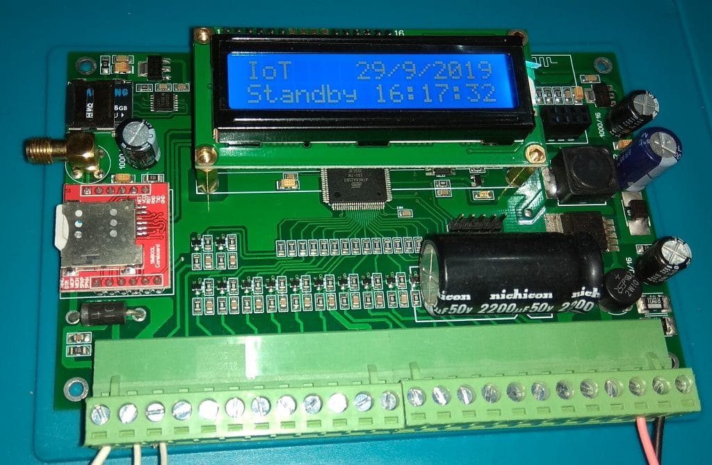
Data-Logger can be different types based on data types. Different sizes, different operating systems. But they all do the same thing in basic. They record data over time. Sometimes, data is stored in local storage and sometimes, data is stored online. Here is an example of IoT based Data-Logger which logs data at an IoT server over the internet.
Data-Logger basic block diagram:
For a basic data logger this block diagram is common which can be used for our own Data-Logger with Arduino too.
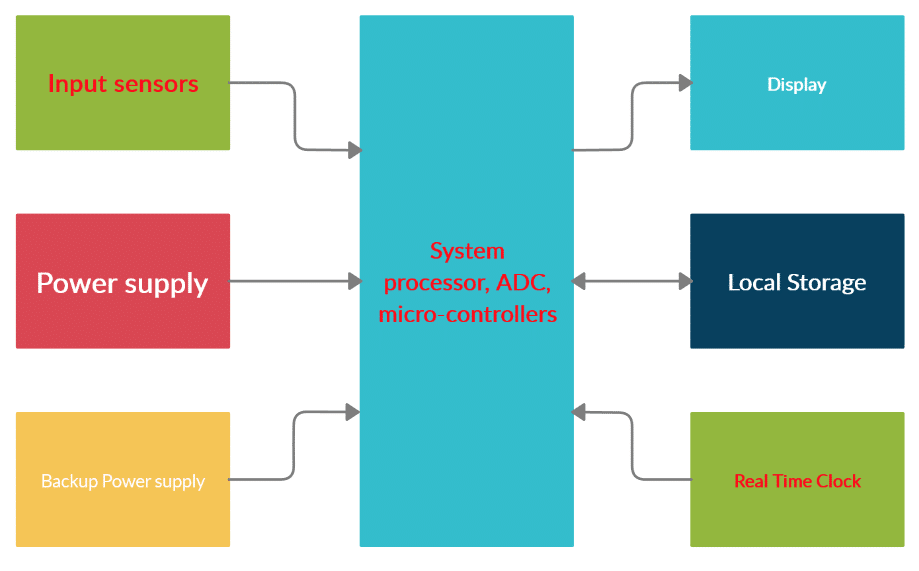
About block diagram:
Most of the data-logger have this block diagram in common. There will be some inputs to sense the data. The inputs can be any type of data depending on the data logger use. These data are collected and processed in the system then stored in local storage and some data-logger sends or stores these data over the cloud or dedicated server. These types of data-logger are called IoT-based data-logger.
Here, in this project, we are going to make a local storage data logger.
Circuit Diagram:
Here is the circuit diagram of our Data-Logger with Arduino:

Here in the circuit diagram, we used ACS712-30A current sensor to sense the current and resistors as the voltage sensor. Arduino UNO is working as our central system controller, ADCs are used to read the values and process inside. Then values are printed on the LCD display. With time reading from DS1307 RTC IC, data is being saved on MMC periodically. The total system runs on a battery and LM7805 based linear voltage regulator is used to proving a regulated 5V DC to MCU and other circuits.
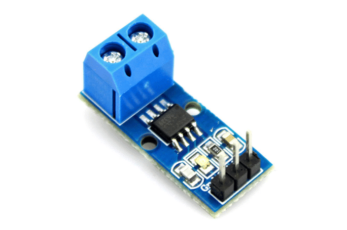
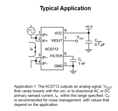
About ACS712-30A:
ACS712 is a hall sensor-based current sensor. This sensor can be used in both AC and DC circuits to sense the current. The 1.2 mΩ internal conductor resistance makes it a low loss current sensor which is ideal in most cases.
Coding:
#include <LiquidCrystal.h>
#include <Wire.h>
#include "RTClib.h"
RTC_DS1307 RTC;
#include <SD.h>
#include <SPI.h>
const int chipSelect = 4;
LiquidCrystal lcd(10, 9, 8, 7, 6, 5);
short display_mode = 0;
int i = 0;
double current = 0.0;
double voltage = 0.0;
double power = 0.0;
int minute1 = 0, minute2 = 0;
int second1 = 0, second2 = 0;
void setup()
{
  lcd.clear();
  RTC.begin();
  lcd.begin(16, 2);
  lcd.setCursor(0, 0);//cr
  lcd.print(F("Solar Datalogger"));
  Serial.begin(9600);
  Serial.println(F("Solar Datalogger project"));
  //RTC.adjust(DateTime(F(__DATE__), F(__TIME__)));//auto update from computer time, run this line only once.
  pinMode(chipSelect, OUTPUT);
  MMC_int(); // mark when simulating only
  Creat_file();// mark when simulating only; Unmark in real hardware
  delay(2000);
  lcd.clear();
  display_mode = 0;
}

void loop()
{

  current = 0;
  for (i = 0; i < 20; i++)
  {
    current += float((2490 - (analogRead(0) * 4.8828125)) / 66.00); //in mV range
    delay(1);
  }
  current /= 20;
  current = abs(current);


  lcd.setCursor(0, 1);
  lcd.print("I:");
  lcd.print(current, 3);

  voltage = 0;
  for (i = 0; i < 20; i++)
  {
    voltage += float(analogRead(1) * 0.54555368); //in mV range
    delay(1);
  }
  voltage /= 20;
  voltage = abs(voltage);

  lcd.setCursor(0, 0);
  lcd.print("V:");
  lcd.print(voltage, 3);

  power = float(voltage * current);
  lcd.setCursor(8, 1);
  lcd.print("P:");
  lcd.print(power, 3);
  lcd.print("W");

  DateTime now = RTC.now();
  lcd.setCursor(11, 0);
  if (display_mode == 0)
  {
    lcd.print(now.hour(), DEC);
    lcd.print(":");
    lcd.print(now.minute(), DEC);
    //lcd.print(":");
    //lcd.print(now.second(), DEC);
  }
  else
  {
    lcd.print(now.day(), DEC);
    lcd.print("/");
    lcd.print(now.month(), DEC);
  }
  second1 = now.second();
  if(second1>=59)second2=0;
  if (second1 >= second2+2)
  {
    if (display_mode == 1)display_mode = 0;
    else if (display_mode == 0)display_mode = 1;
    second2 = second1;
    if(second1>=59)second2=0;
    lcd.clear();
    File dataFile = SD.open("datalog.txt", FILE_WRITE);
    if (dataFile)
    {
      Serial.println(F("Saving data on SD card"));
      DateTime now = RTC.now();
      dataFile.print(now.hour());
      dataFile.print(":");
      dataFile.print(now.minute());
      dataFile.print(":");
      dataFile.print(now.second());
      dataFile.print(",  ");

      dataFile.print(now.day());
      dataFile.print("/");
      dataFile.print(now.month());
      dataFile.print("/");
      dataFile.print(now.year());
      dataFile.print("     ");
      dataFile.print(voltage,3);
      dataFile.print("  ");
      dataFile.print(current,3);
      dataFile.print("  ");
      dataFile.print(power,3);
      dataFile.println("  ");
      dataFile.close(); // close the file
      Serial.println(F("Done."));
      dataFile.close();
      lcd.clear();
    }
    lcd.clear();
  }


}//loop


void Creat_file()
{
  File dataFile = SD.open("datalog.txt", FILE_WRITE);
  if (dataFile)
  {
    dataFile.println(" Data Logger for Soler energy started_");
    dataFile.println("Time >> Date  >>  Voltage(volts)  >>  Current(ampere) >>  Power(watt)  ");
    dataFile.close();
    Serial.println("file found and ready to write");
  }
}


void MMC_int()
{
  Serial.print(F("Initializing SD card..."));
  // see if the card is present and can be initialized:
  if (!SD.begin(chipSelect))
  {
    Serial.println(F("Card failed, or not present"));
    // don't do anything more:
    while (1);
  }
  Serial.println(F("card initialized."));
}

//
No special code is used in this project. All codes are very simple and arranged in the easiest way. When your PCB is ready to test, first of all, you need to set your clock. For that, you need to unmask this line:
RTC.adjust(DateTime(F(__DATE__), F(__TIME__)));//auto update from computer time
Once your time is set, then mask the line again. Everything will be fine.
PCB:
I made this project in real life and used it as a product which is being used since 2017 locally. Here is the PCB file of this project.

After making the project in hardware:

You can check this page for PCB design and PCB Software Help.
Test result:
I used this project as a product in a solar test field. Where it is used to log the voltage and current reading. But at that time, I did not keep any video of the project. But today, I can share the simulated result.
Conclusion:
In the end, I can say that as I made this project real so you can use it too in your project without any hesitation. It will work fine if you follow everything I said.
I hope this project was helpful to you. If you make one for yourself, it will be a great pleasure for me. Anywhere you need help, let me know. Please share this project and subscribe to my blog. Thank you.
Liked this article? Subscribe to our newsletter:
or,
Visit LabProjectsBD.com for more inspiring projects and tutorials.
Thank you!
Check this out: 5 coolest multimeters you can buy


2 Comments
Neill · 29/07/2021 at 6:51 pm
The code working.. thanks man
MKDas · 31/07/2021 at 9:39 pm
You are welcome