In this article, we are going to make our own control card for coffee vending machines. This machine is nowadays very common in shops and restaurants. Small businesses can be started with this machine. Here let’s make a simple functional control card for the coffee vending machine.
⚠️Disclaimer:
Working with electricity involves serious risk. Ensure you have the necessary skills and take proper safety precautions before attempting any electrical projects. Proceed at your own risk — the author assumes no responsibility for any damage, injury, or issues resulting from the use or misuse of the information provided.
All content on this website is original and protected by copyright. Please do not copy or reproduce content without permission. While most of the resources shared here are open-source and freely accessible for your learning and benefit, your respect for our intellectual effort is appreciated.
If you find our tutorials helpful, consider supporting us by purchasing related materials or sharing our work — it helps keep the content flowing.
Need help or have questions? Leave a comment below — the author is always happy to assist!
Table of Contents
About the coffee vending machine:
A coffee vending machine usually dispenses hot coffee. But getting tea and hot water is optional. Most of the vending machines have other features like milk, coffee-mate, etc. More elaborately sugar, flavor, etc. also can be added.

Some of these vending machines may have a keypad for passwords or an RFID card scanning option. But in a very simple one, only a few basic options are kept.
These are:
- Adding Coffee powder
- Adding Tea powder
- Adding Water
- Adding Sugar
- Mixing
Sometimes, sugar is premixed with tea/coffee. In this case, the mixture is called a premix. Here in South Asia, most of the coffee vending machines use premixed powder for coffee & tea separately.
In this article, we are going to make the last type which uses premixed powders. In this case, we have only a few devices to control. We can say these devices like this:
Devices:
- Premix1
- Water1
- Mixure1
- Premix2
- Water2
- Mixure2
Mixure1&2 are motors to drive and the rest of the devices are valves. We can use simple relays to drive these loads.
Premix1, Water1, and Mixure1 these are making coffee, and Premix2, Water2, and Mixure2 are making tea. Besides, to get hot water only, Water1 & Water2 work simultaneously.
Now, we can draw our circuit diagram.
You may find this article helpful: PICKit2 colon Simplified
Circuit Diagram our coffee vending machine:

Relays are presented by LEDs to simplify the circuit diagram so that you can understand it clearly. I’ve designed this circuit in PCB. You can watch this video to understand as well as practice making one for yourself.
The video language is Bengali. If you do not understand kindly read the subtitles.
Programming & Simulation:
Here in this project, I used mikroC pro for PIC as the compiler and proteus 8.9 as the simulator.
/*******************************************************************************
Program for, Coffee Vending Machine
Program Written by_ Engr. Mithun K. Das
MCU:PIC16F877A; X-tal:20MHz; Compiler: mikroC pro for PIC v7.6.0
Date: 24-12-2020
*******************************************************************************/

// LCD module connections
sbit LCD_RS at RB5_bit;
sbit LCD_EN at RB4_bit;
sbit LCD_D4 at RB3_bit;
sbit LCD_D5 at RB2_bit;
sbit LCD_D6 at RB1_bit;
sbit LCD_D7 at RB0_bit;

sbit LCD_RS_Direction at TRISB5_bit;
sbit LCD_EN_Direction at TRISB4_bit;
sbit LCD_D4_Direction at TRISB3_bit;
sbit LCD_D5_Direction at TRISB2_bit;
sbit LCD_D6_Direction at TRISB1_bit;
sbit LCD_D7_Direction at TRISB0_bit;
// End LCD module connections

void Lcd_COut(char row, char col, const char *cptr)
{
  char chr = 0;             //first, it is used as empty string
  Lcd_Out(row, col, &chr);  //nothing to write but set position.
  for ( ; chr = *cptr ; ++cptr ) Lcd_Chr_CP(chr); //out in loop
}


//define buttons here
#define    TEA          RA0_bit
#define    COFFEE       RA1_bit
#define    HALF         RA2_bit
#define    HOT_WATER    RA3_bit

//define outputs here
#define    Buzzer       RD3_bit
#define    Relay1       RC4_bit
#define    Relay2       RD2_bit
#define    Relay3       RC5_bit
#define    Relay4       RC6_bit
#define    Relay5       RC7_bit
#define    Relay6       RD4_bit


int rl1_counter;// 50 = 5 sec    //premix1
int rl2_counter;                 //water1
int rl3_counter;                 //wiper1
bit tea_activation;

int rl4_counter;// 50 = 5 sec    //premix2
int rl5_counter;                 //water2
int rl6_counter;                 //wiper2

bit coffee_activation;
bit hot_water_activation;
bit edit_mode;
int division=1;

int edit_mode_entry_counter=0;
short edit_page=0;


#include "subfunctions.h"
I’ve described the complete code with simulation side by side. Please watch these videos to understand the code. Please watch these videos to understand the code.
Or you can get the complete code from here.
PCB Design:
I’ve designed a PCB for this project. Here is the PCB:

You can use this PCB design to make your own PCB or alternatively, you can buy my design from here.
Professional Product:


Features:
- Fully customized time setting
- Half/Full cup Tea, Coffee, Water dispensing
- Water heater control
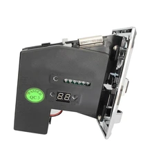
- Coin acceptor
- Coffee & tea counter
- Total Counter
- 12V,24V, or AC220V switching option
- Password protection.
#If you need a ready coffee vending machine control card send a message to WhatsApp.
Conclusion:
In the end, we can say that if anyone reads this article with concentration, and watch the videos carefully it is not a difficult job to make his/her own control card.


I hope this project was helpful to you. If you make one for yourself, it will be a great pleasure for me. Anywhere you need help, let me know. Please share this project and subscribe to my blog. Thank you.
For more useful articles, don’t forget to subscribe.
Liked this article? Subscribe to our newsletter:
or,
Visit LabProjectsBD.com for more inspiring projects and tutorials.
Thank you!
Read More:
- Connect to Raspberry Pi from your Laptop/Desktop using VNC Viewer
- How to reduce noise from DC motor
- Read ThingSpeak Channel using ESP8266 and Arduino
- Reading SMS with Arduino
- Caller ID detection using Arduino
- Energy-saving innovative power switch for microcontroller circuit
- STM32 as USB Device
- Send SMS from Raspberry Pi using the GSM module
- Make an MPPT Solar charge Controller with Synchronous Buck Converter


8 Comments
Joy · 24/02/2021 at 5:12 pm
Nice….Go ahead.. Thank you.
Ajape · 03/03/2021 at 11:12 am
Good day engr Mithun. Thanks for this new development. How I wish I could understand Indian language, as I am from Nigeria, but I don’t really grab your explanation, and the code in the video is not clearly seen and I really want to learning it and do it. I have practice many of your projects on your blogs, based PIC controller. Please. If you could send me the source code and the schematic diagram of this COFFEE VENDING MACHINE CONTROL CIRCUIT. my Gmail address is: [email protected]
Secondly sir. There is one project you had posted in your previous blogs: DIGITAL MULTIMETER” I have been searching for it but I couldn’t find it again. Please I need your help if you could send them to me, I would be very grateful sir. Thanks.
Mithun K. Das · 06/03/2021 at 5:26 am
OK.
Ayush Dubey · 05/10/2021 at 2:13 am
Sir can you please send me the source code and the schematic diagram of this COFFEE VENDING MACHINE CONTROL CIRCUIT. My Gmail id is [email protected]
I want to complete my major project.
md Nurul abbas · 11/06/2023 at 2:38 am
sir iam interest for your coffee vanding pcb. i wan tis project
i from Chittagong
MKDas · 11/06/2023 at 6:56 pm
Professional one is not for project selling. You can get ready product.
Prathamesh Patil · 23/09/2024 at 2:47 pm
Sir can you please send mi this project all component list with their specifications Ani proper connection circuit diagram And working video of this project I want to make my mini project please help me sir send this all materials in ma email id – [email protected].
Thank you
MKDas · 23/09/2024 at 9:02 pm
Hello, please learn it and make it. Or get help from professionals. Learning and DIY is free.