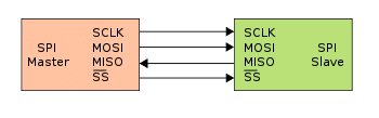
Serial Peripheral Interface (SPI) is a synchronous serial communication interface, used to communicate between microcontrollers and peripheral devices such as sensors, displays, and memory. STM32 microcontrollers support SPI communication, which enables fast and reliable data transfer between devices. In this article, we will explore SPI communication with STM32 microcontrollers, including hardware setup, software configuration, and code implementation.
⚠️Disclaimer:
Working with electricity involves serious risk. Ensure you have the necessary skills and take proper safety precautions before attempting any electrical projects. Proceed at your own risk — the author assumes no responsibility for any damage, injury, or issues resulting from the use or misuse of the information provided.
All content on this website is original and protected by copyright. Please do not copy or reproduce content without permission. While most of the resources shared here are open-source and freely accessible for your learning and benefit, your respect for our intellectual effort is appreciated.
If you find our tutorials helpful, consider supporting us by purchasing related materials or sharing our work — it helps keep the content flowing.
Need help or have questions? Leave a comment below — the author is always happy to assist!
Hardware Setup:
To use SPI communication with STM32 microcontrollers, we need to set up the hardware components properly. In this example, we will use an STM32F407VG board and an SPI flash memory chip (Winbond W25Q128FV). Here are the steps for hardware setup:

- Choose the SPI pins: The STM32F407VG board has multiple pins that support SPI communication. We will use SPI1, which has the following pins:
- PA5: SPI1_SCK
- PA6: SPI1_MISO
- PA7: SPI1_MOSI
- PB6: SPI1_CS
- Connect the SPI pins: We will use jumper wires to connect the SPI pins of the STM32F407VG board to the SPI flash memory chip. The connections are as follows:
- PA5 (SPI1_SCK) -> CLK
- PA6 (SPI1_MISO) -> SO
- PA7 (SPI1_MOSI) -> SI
- PB6 (GPIO) -> CS
Software Configuration:
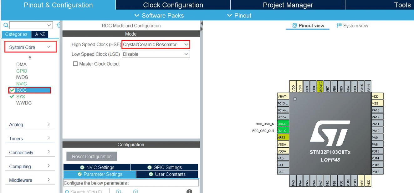
After setting up the hardware components, we need to configure the software to use SPI communication with STM32 microcontrollers. We will use the STM32CubeIDE tool to generate the initialization code for us. Here are the steps for software configuration:
- Create a new STM32CubeIDE project: We will create a new project for the STM32F407VG board using STM32CubeIDE. We will select the STM32F407VG board, the STM32Cube firmware package, and the C language.
- Generate the initialization code: We will use the CubeMX tool to generate the initialization code for the SPI peripheral and the GPIO pin. We will select the SPI1 peripheral, configure its parameters such as clock source, clock polarity, and clock phase, and generate the code. We will also select the PB6 GPIO pin, configure it as output, and generate the code.
- Implement the SPI communication protocol: Once the initialization code is generated, we can implement the SPI communication protocol in the main function.
Here is the code for the main function:
Example code in STM32CubeIDE:
#include "main.h"
#include "stm32f4xx_hal.h"

SPI_HandleTypeDef hspi1;

void SystemClock_Config(void);
static void MX_GPIO_Init(void);
static void MX_SPI1_Init(void);

int main(void)
{
  HAL_Init();

  SystemClock_Config();

  MX_GPIO_Init();
  MX_SPI1_Init();

  uint8_t data[256] = {0};
  uint8_t txData[4] = {0x03, 0x00, 0x00, 0x00};

  HAL_GPIO_WritePin(GPIOB, GPIO_PIN_6, GPIO_PIN_RESET);
  HAL_SPI_Transmit(&hspi1, txData, 4, 1000);
  HAL_SPI_Receive(&hspi1, data, 256, 1000);
  HAL_GPIO_WritePin(GPIOB, GPIO_PIN_6, GPIO_PIN_SET);

  while (1)
  {
      //your codes
  }
}

...
This will transmit and receive the data. You can use this with other parts of your code to use SPI communication. Hope this will help you. Thanks.
Liked this article? Subscribe to our newsletter:
or,
Visit LabProjectsBD.com for more inspiring projects and tutorials.
Thank you!
You can check similar articles too:


0 Comments