In the previous chapter, we learned about the Timer interrupt and also learned how to use Timer0 as a timer interrupt. In this chapter, we’ll use Timer0 as a counter which is another feature of Timers in microcontrollers. This will help us count pulses or frequencies. Also, we’ll see an example using Timer0 as a counter. So let’s start!
⚠️Disclaimer:
Working with electricity involves serious risk. Ensure you have the necessary skills and take proper safety precautions before attempting any electrical projects. Proceed at your own risk — the author assumes no responsibility for any damage, injury, or issues resulting from the use or misuse of the information provided.
All content on this website is original and protected by copyright. Please do not copy or reproduce content without permission. While most of the resources shared here are open-source and freely accessible for your learning and benefit, your respect for our intellectual effort is appreciated.
If you find our tutorials helpful, consider supporting us by purchasing related materials or sharing our work — it helps keep the content flowing.
Need help or have questions? Leave a comment below — the author is always happy to assist!
If you missed the previous chapter please have a look from here if you want.
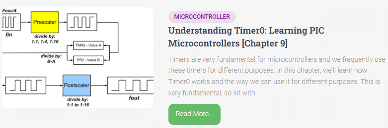
Table of Contents
Timer0 as a counter:
Timer0 in a PIC microcontroller serves as a versatile counter with various applications in timing, counting, and generating precise intervals. Operating as an 8-bit timer, Timer0 can count up to 255 cycles before overflowing. It’s commonly used for tasks like generating precise time delays, measuring external events, or creating periodic interrupts for system timing.
In its counter mode, Timer0 can count external events or internal clock cycles based on the configuration. It can be configured to increment on rising or falling edges of an external signal, making it adaptable for different input sources.
With its compact size and flexibility, Timer0 plays a crucial role in many embedded systems, providing fundamental timing functionality essential for tasks ranging from simple blinking LEDs to more complex event scheduling and synchronization in microcontroller-based applications.
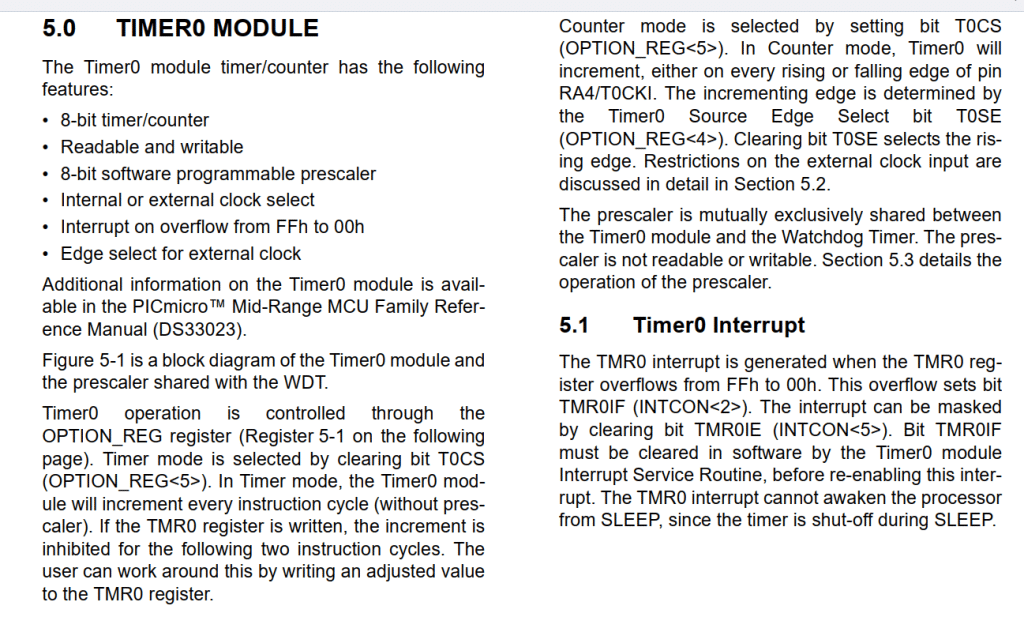
The Timer0 module of the microcontroller can be used in both ways. As a timer when it counts the TMR variable itself by the time settings and as a counter, it can count the signal in a certain time. Simply, it is a way of counting pulses by the module.
If you see the datasheet, you can get the timer0 details:
Uses of Timer Counter:
The Timer Counter module in PIC microcontrollers serves a crucial role in various applications, offering precise timing and counting capabilities. Its versatility enables it to be employed in a multitude of scenarios:
- Timing and Delays: One of the primary uses of the Timer Counter is to generate accurate time delays. This feature is handy in applications requiring precise timing, such as generating PWM signals, controlling motor speed, or initiating specific actions after a predefined period.
- Pulse Width Modulation (PWM): PWM signals are essential for controlling the speed of motors, the brightness of LEDs, or generating analog output voltages. The Timer Counter module facilitates PWM generation by producing pulse-width modulated signals with adjustable duty cycles.
- Event Counting: The Timer Counter can also serve as an event counter, tallying external events such as sensor inputs, button presses, or any other digital signal transitions. This functionality finds applications in tasks like monitoring system usage, counting objects on a conveyor belt, measuring the frequency of an incoming signal, and so on.
Overall, the Timer Counter module in PIC microcontrollers offers a versatile set of features that cater to diverse timing, counting, and synchronization requirements across a wide range of applications, making it a fundamental component in embedded systems design.
Let’s be practical to understand it.
A frequency meter:
This is a common use of event counting using Timer0 as a counter and it’s useful too. So let’s make it.
Code:
/*
Program for "Timer0 as a counter"
Program written by_ Engr. Mithun K. Das|| [email protected]
MCU:PIF16F76; Xtal:8MHz; mikroC pro for PIC v7.6.0
Date:28-01-2024
*/


void main()
{
  TRISA = 0xFF;//all input
  TRISB = 0x00;//all output
  TRISC = 0x00;//all output
  ADCON1 = 0x07;//all digital I/O
  ADCON0 = 0x00;//turn off ADC
  PORTB = 0x00;//clear port
  PORTC = 0x00;//clear port

  //configure timer as counter
  OPTION_REG = 0b00110000;

  while(1)
  {
     TMR0 = 0;//clear value
     Delay_ms(1000);//wait one Second
     PORTB = TMR0;//print on PORTB
  }
}
Output:
Explanation:
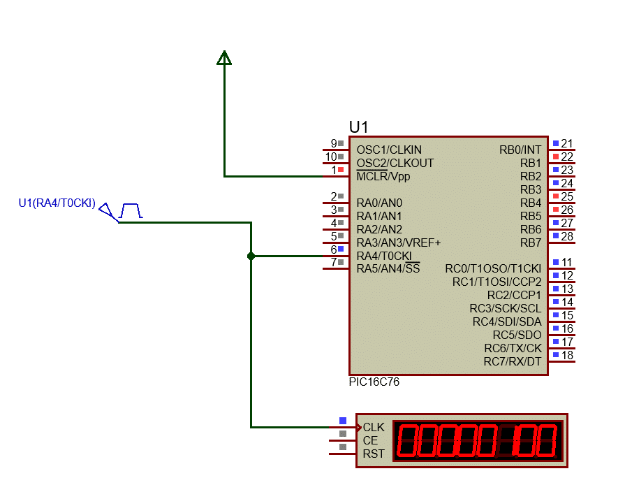
The code is very simple, just set the I/O then configure the timer as a counter. Here, the Timer0 input pin is RA4/T0CKI pin. So we need to feed the pulse in this pin. Note that this pin is an open drain, so we may need to use a pull-up resistor practically.
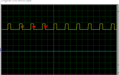
Here, I provided a 100Hz pulse to the T0CKI pin and it has printed the value in PORTB [RB0>>LSB & RB7 >>MSB].
So in binary, it is 00110010 which is 50 in decimal. But why? In the OPTION_REG register settings, we selected to count increment on high-to-low transition on the T0CKI pin. So in real life, the 100Hz signal has 50 high-to-low transitions.
Now we can read the pulses in a period. To use this in the frequency meter, we may need to interface LCD or similar displays with the MCU.
Notes:
Learning about Timer0 is the first step to understanding how timers work in PIC microcontrollers. Timer1 and Timer2 are similar to Timer0, but they can do more things with greater detail.
Timer0 teaches the basics, but Timer1 and Timer2 go deeper into how to manage time in different applications. They add to what Timer0 can do, giving you more control and accuracy for tasks that depend on timing.
Some timers can be stopped while they’re running, but others keep going no matter what. However, the main ideas on how to use them—for example, how to set them up, start them, or use interruptions—stay the same for all timers.
In short, when you understand Timer0 well, it becomes much easier to use Timer1 and Timer2 and take advantage of their extra features for a variety of projects.
Conclusion:
The same configuration can be used in button press counts or for example quiz counters. But whatever it is, if you understand how to use it then you can implement the knowledge for different purposes. So it’s your turn now to utilize it. See you soon with another chapter…
You may read these too:
- Understanding Timer0: Learning PIC Microcontrollers [Chapter 9]
- Learning ADC of PIC microcontrollers: Learning PIC microcontrollers [Chapter 8]
- Learning PIC MCU: How to interface buttons with microcontrollers [Chapter 7]
- Learning PIC MCU: Interfacing passive components with Microcontrollers [Chapter 6]
Liked this article? Subscribe to our newsletter:
or,
Visit LabProjectsBD.com for more inspiring projects and tutorials.
Thank you!


0 Comments