In the learning PIC MCU series, in this chapter, we’ll learn about interfacing passive components with microcontrollers. This chapter is very very important to learn about the basic electronics so that you do not burn any MCU or devices. So do not skip this chapter.
⚠️Disclaimer:
Working with electricity involves serious risk. Ensure you have the necessary skills and take proper safety precautions before attempting any electrical projects. Proceed at your own risk — the author assumes no responsibility for any damage, injury, or issues resulting from the use or misuse of the information provided.
All content on this website is original and protected by copyright. Please do not copy or reproduce content without permission. While most of the resources shared here are open-source and freely accessible for your learning and benefit, your respect for our intellectual effort is appreciated.
If you find our tutorials helpful, consider supporting us by purchasing related materials or sharing our work — it helps keep the content flowing.
Need help or have questions? Leave a comment below — the author is always happy to assist!
Table of Contents
Previous chapter:
If you missed the previous chapter, you can read it here.
Till the last chapter, we have learned how we can write code for simple tasks like blinking a LED. Now, in this chapter, we’ll learn about interfacing passive components with microcontrollers.
Key points to keep in mind:
There are several points to keep in mind when you need to interface a component with MCU. But these are the basics to follow.
- MCU pin voltage
- Sink & source current
- Response time
- Operating voltage range
- Operating temperature range
MCU pin voltage and also the operating voltage range of the MCU are vital things for any microcontroller. Some of them work at 3.3V, and some work at 5V. So you must be sure what is the range of your microcontroller.
Then the next term is the Sink and Source current. When you are using any components, a current need to drive that or do something. But there is a limit to that current in each pin of the microcontroller. Some MCU works at 12.5mA, some can deliver 25mA, and some even more. So it is the second vital point which is the current limit.
Then the temperature range and response time. As you may use the MCU in different weather, so in some cases this can be a problem if you use an MCU in a high-temperature range out of its capacity. So you should know that too.
Examples of some common interfaces:
Interfacing a LED:
LED is one of the most used components with a microcontroller. Now, you may find that most of the MCU can drive LEDs directly from its pin. But the problem is, if LEDs are driven like that, will they sustain?
This actually depends on that particular LED. Some LEDs are capable of taking 2A, some are fine under 2mA. So first check the datasheet of that LED then select a sweet point to fix the right current. For common 5mm LEDs, we usually use a resistor in series. And we select that resistor in a value so that the current is around 5~8mA. Like this image.
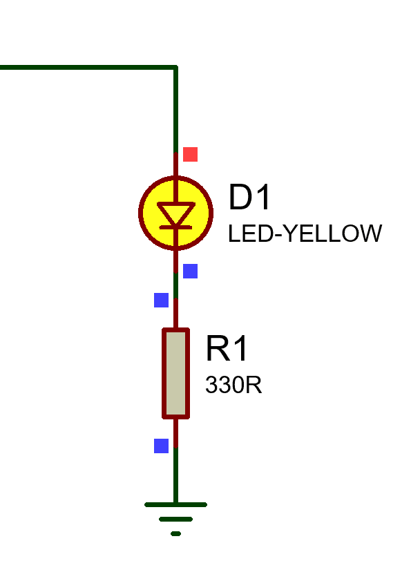
Here, the MCU pin voltage was 5V. So max current through the LED will be:
5/330 = 15mA and minimum: (5.0-LED forward voltage drop)/330Ohm.
For these types of loads, you should not exceed the pin current over 12.5mA. This will keep the MCU protected from heat generation.
Interfacing Transistor:
Transistors are current biased, I hope you know that. Some transistors can work even with the uA range. But some especially the power transistor work over 1A base current. So when you need to drive a power transistor that works over 10mA base current you should use an amplifier circuit to gain the current. Here is an example of that:
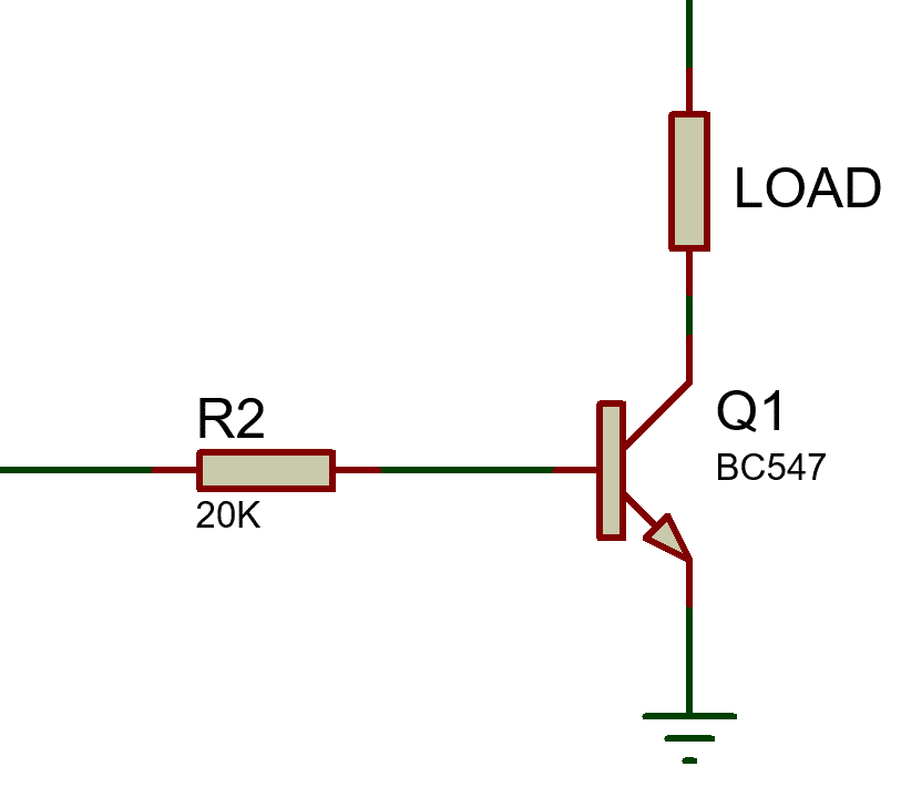
Here, BC547 is a To-92 package high-gain general-purpose transistor and its gain is around 400 and the max collector current is 100mA. That means its max base current is 100/400 = 0.25mA only. So, you can use a resistor that can limit the current up to 0.25mA.
Base Resistor = (5V-0.7V)/0.25mA = 17.2KΩ.
So, based on your load, you should select this resistor in the right value. Then the transistor and also the MCU will be safe.
Now, if you need to drive a transistor that needs more biasing current then?
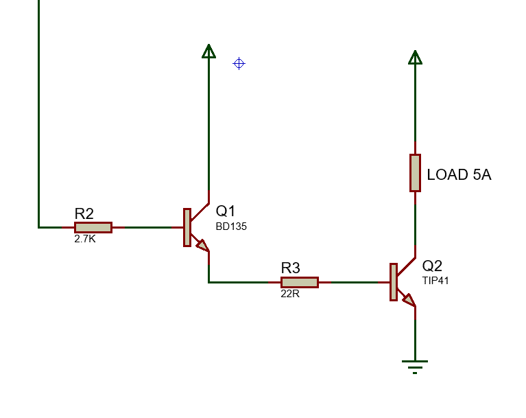
In this case, first start from the load current to what to drive with the power transistor TIP41. Here, the gain of TIP41 is only 30. So, you need 5/30 = 0.167A base current to bias this transistor. Now of course the MCU can not deliver that much current. So, we have to use a transistor that can provide the biasing current of TIP41.
BD135 which gain is around 100. And for 0.16A, it can deliver that much if we set the base resistor around 2.7KOhm for a 5V pin.
Note here, from calculations, we can find a resistor that is near or different from the standard. So we must select the standard values and also keep in mind the tolerance of the resistors. So it’s a matter of experience to select the nearby standard values. But you should follow the basics first, then you will learn this.
You can get it that the transistors are not that efficient for switching purposes but in some cases, transistors are good. And nowadays, it’s good practice to use MOSFETs to switch anything when you are using MCU. MOSFETs are not current-driven like transistors. It can work with voltage signals.
Interfacing MOSFETs :
Interfacing MOSFETs are super easy compared to the transistors. But not that easy you think. Each MOSFET has a range of Gate voltage to keep it safe and use the proper switching capacity. Let’s check these.
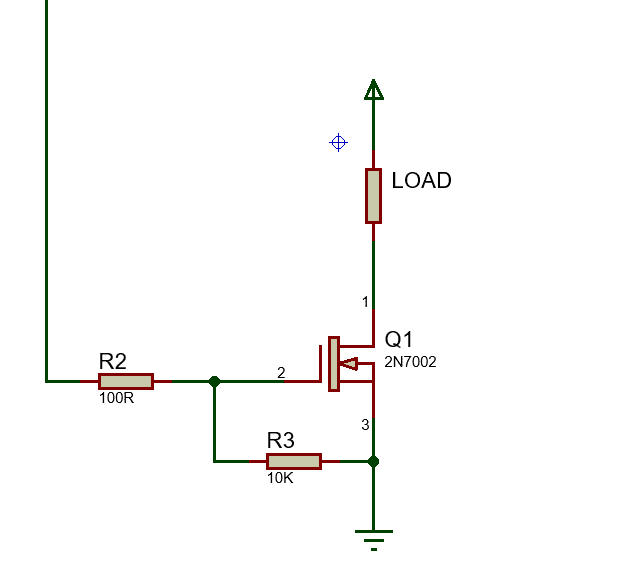
If you see the datasheet of 2N7002, you can find that it will turn on at 4.5V and the Rds will be even lower at 10V. So if your load is light, you can use it at 4.5V. In this case, you can use a small range resistor to feed the gate voltage from 5V but you must use a resistor from Gate to Source to discharge the gate. For MOSFETs, this discharging resistor is more important than the current limiting resistor.
But in those cases, the MOSFET gate voltage needs to be higher than the MCU voltage like this one:
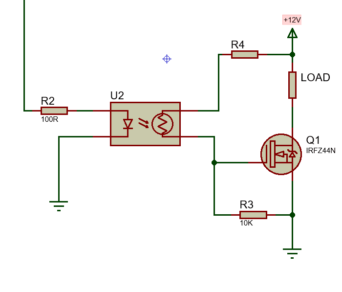
You must use something to increase the gate voltage like an opto-coupler. Here as you can see, I used an optocoupler to bypass the +12V to the gate of the MOSFET, and do not forget the gate discharging resistor again here.
Interfacing Relays:
Relays are one of the common devices we need to use with MCUs.
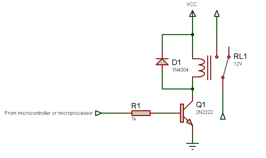
For relays, first, you must use a Transistor or MOSFET to drive the relay coil, and second, to protect that transistor/MOSFET or even other components you must use a diode in reverse with the relay coil. This is very important otherwise the back EMF generated while the relay turns off will damage the transistor or even the MCU or other components of your circuit.
Conclusion:
These are the basic and common components you will need to use with your circuits. And when there are different types of components that need to interface, I’ll discuss that later on. Now you can practice interfacing LEDs, Transistors, and Relays with your previous blinking project. In the next chapter, we’ll see how we can take inputs to the microcontroller. See you soon.
Read more on:
- Learning PIC Microcontrollers Programming in C: Chapter 1
- Learning PIC Microcontrollers Programming in C: Chapter 2
- Learning PIC Microcontrollers Programming in C: Chapter 3
- Learning PIC Microcontrollers Programming in C: Chapter 4
- Learning PIC Microcontrollers Programming in C: Chapter 5
- Learning PIC Microcontrollers Programming in C: Chapter 7
Liked this article? Subscribe to our newsletter:
or,
Visit LabProjectsBD.com for more inspiring projects and tutorials.
Thank you!


2 Comments
Asimiyu · 21/05/2023 at 12:55 pm
Thank you sir for this educational tutorials based embedded systems and programming from the scratch to finish. We are following you. God bless you with more knowledge
iffi · 22/05/2023 at 6:48 am
Thank you Sir. I appriciate your Hard work. God bless you.